Valid 200-301 Dumps shared by ExamDiscuss.com for Helping Passing 200-301 Exam! ExamDiscuss.com now offer the newest 200-301 exam dumps, the ExamDiscuss.com 200-301 exam questions have been updated and answers have been corrected get the newest ExamDiscuss.com 200-301 dumps with Test Engine here:
Access 200-301 Dumps Premium Version
(1255 Q&As Dumps, 35%OFF Special Discount Code: freecram)
<< Prev Question Next Question >>
Question 4/773
Lab Simulation 40
Guidelines
This is a lab item in which tasks will be performed on virtual devices.
- Refer to the Tasks tab to view the tasks for this lab item.
- Refer to the Topology tab to access the device console(s) and perform the tasks.
- Console access is available for all required devices by clicking the device icon or using the tab(s) above the console window.
- All necessary preconfigurations have been applied.
- Do not change the enable password or hostname for any device.
- Save your configurations to NVRAM before moving to the next item.
- Click Next at the bottom of the screen to submit this lab and move to the next question.
- When Next is clicked, the lab doses and cannot be reopened.
Topology
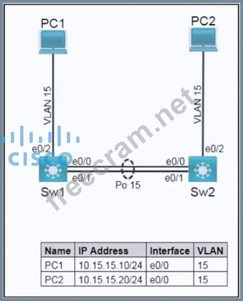
Tasks
Task 1
Configure trunks between Sw1 and Sw2 on ports E0/0 and E0/1 using the IEEE standard frame tagging method.
- Add VLAN 45 as untagged on the trunk ports.
- Only extend VLAN 15 and the untagged VLAN across the trunk.
- Verify that PC1 is capable of pinging PC2.
Task 2
On Sw1 and Sw2, use IEEE 802.3ad link aggregation.
- Combine E0/0 and E0/1 into a single logical link while leaving the trunk configurations intact.
- Assign number 15 to the link.
- Both links must negotiate aggregation.
Guidelines
This is a lab item in which tasks will be performed on virtual devices.
- Refer to the Tasks tab to view the tasks for this lab item.
- Refer to the Topology tab to access the device console(s) and perform the tasks.
- Console access is available for all required devices by clicking the device icon or using the tab(s) above the console window.
- All necessary preconfigurations have been applied.
- Do not change the enable password or hostname for any device.
- Save your configurations to NVRAM before moving to the next item.
- Click Next at the bottom of the screen to submit this lab and move to the next question.
- When Next is clicked, the lab doses and cannot be reopened.
Topology
Tasks
Task 1
Configure trunks between Sw1 and Sw2 on ports E0/0 and E0/1 using the IEEE standard frame tagging method.
- Add VLAN 45 as untagged on the trunk ports.
- Only extend VLAN 15 and the untagged VLAN across the trunk.
- Verify that PC1 is capable of pinging PC2.
Task 2
On Sw1 and Sw2, use IEEE 802.3ad link aggregation.
- Combine E0/0 and E0/1 into a single logical link while leaving the trunk configurations intact.
- Assign number 15 to the link.
- Both links must negotiate aggregation.
Correct Answer:
See the below explanation
Explanation:
Task 1: Configure Trunks
We will configure trunk links between Sw1 and Sw2 on interfaces E0/0 and E0/1, using the IEEE
802.1Q standard for VLAN tagging. Additionally, VLAN 45 will be configured as untagged, while only VLANs 15 and 45 will be allowed across the trunk.
Steps for Task 1 on Sw1:
1. Access the trunk interfaces:
interface range Ethernet0/0 - 1
switchport mode trunk
switchport trunk native vlan 45
switchport trunk allowed vlan 15,45
2. Verify trunk configuration:
show interfaces trunk
Steps for Task 1 on Sw2:
1. Access the trunk interfaces:
interface range Ethernet0/0 - 1
switchport mode trunk
switchport trunk native vlan 45
switchport trunk allowed vlan 15,45
2. Verify trunk configuration:
show interfaces trunk
3. Test PC1 to PC2 Connectivity: On PC1, ping PC2 using its IP address 10.15.15.20:
ping 10.15.15.20
Task 2: IEEE 802.3ad Link Aggregation
Now we configure link aggregation (LACP) between Sw1 and Sw2 on interfaces E0/0 and E0/1, forming a logical link called Port-Channel 15.
Steps for Task 2 on Sw1:
1. Enable LACP and assign to a port-channel:
interface range Ethernet0/0 - 1
channel-group 15 mode active
2. Configure the port-channel interface as a trunk:
interface Port-channel15
switchport mode trunk
switchport trunk native vlan 45
switchport trunk allowed vlan 15,45
3. Verify the LACP configuration:
show etherchannel summary
Steps for Task 2 on Sw2:
1. Enable LACP and assign to a port-channel:
interface range Ethernet0/0 - 1
channel-group 15 mode active
2. Configure the port-channel interface as a trunk:
interface Port-channel15
switchport mode trunk
switchport trunk native vlan 45
switchport trunk allowed vlan 15,45
3. Verify the LACP configuration:
show etherchannel summary
Verification of Configuration
1. Trunk Verification: On both switches, confirm that the trunk is operational with VLANs 15 and
45 allowed:
show interfaces trunk
2. Port-Channel Verification: Confirm that the port-channel is active and operational:
show etherchannel summary
3. Ping Test: Verify that PC1 (10.15.15.10) can ping PC2 (10.15.15.20):
ping 10.15.15.20
Explanation:
Task 1: Configure Trunks
We will configure trunk links between Sw1 and Sw2 on interfaces E0/0 and E0/1, using the IEEE
802.1Q standard for VLAN tagging. Additionally, VLAN 45 will be configured as untagged, while only VLANs 15 and 45 will be allowed across the trunk.
Steps for Task 1 on Sw1:
1. Access the trunk interfaces:
interface range Ethernet0/0 - 1
switchport mode trunk
switchport trunk native vlan 45
switchport trunk allowed vlan 15,45
2. Verify trunk configuration:
show interfaces trunk
Steps for Task 1 on Sw2:
1. Access the trunk interfaces:
interface range Ethernet0/0 - 1
switchport mode trunk
switchport trunk native vlan 45
switchport trunk allowed vlan 15,45
2. Verify trunk configuration:
show interfaces trunk
3. Test PC1 to PC2 Connectivity: On PC1, ping PC2 using its IP address 10.15.15.20:
ping 10.15.15.20
Task 2: IEEE 802.3ad Link Aggregation
Now we configure link aggregation (LACP) between Sw1 and Sw2 on interfaces E0/0 and E0/1, forming a logical link called Port-Channel 15.
Steps for Task 2 on Sw1:
1. Enable LACP and assign to a port-channel:
interface range Ethernet0/0 - 1
channel-group 15 mode active
2. Configure the port-channel interface as a trunk:
interface Port-channel15
switchport mode trunk
switchport trunk native vlan 45
switchport trunk allowed vlan 15,45
3. Verify the LACP configuration:
show etherchannel summary
Steps for Task 2 on Sw2:
1. Enable LACP and assign to a port-channel:
interface range Ethernet0/0 - 1
channel-group 15 mode active
2. Configure the port-channel interface as a trunk:
interface Port-channel15
switchport mode trunk
switchport trunk native vlan 45
switchport trunk allowed vlan 15,45
3. Verify the LACP configuration:
show etherchannel summary
Verification of Configuration
1. Trunk Verification: On both switches, confirm that the trunk is operational with VLANs 15 and
45 allowed:
show interfaces trunk
2. Port-Channel Verification: Confirm that the port-channel is active and operational:
show etherchannel summary
3. Ping Test: Verify that PC1 (10.15.15.10) can ping PC2 (10.15.15.20):
ping 10.15.15.20


- Question List (773q)
- Question 1: Drag and Drop Question Drag and drop the RF terms from the l...
- Question 2: What are two benefits of private IPv4 IP addresses? (Choose ...
- Question 3: Which virtualization technology requires a base OS installat...
- Question 4: Lab Simulation 40 Guidelines This is a lab item in which tas...
- Question 5: Which NTP command configures the local devices as an NTP ref...
- Question 6: Why do large OSPF networks use a hierarchical design? (Choos...
- Question 7: Lab Simulation 41 Guidelines This is a lab item in which tas...
- Question 8: Refer to the exhibit. Which routes are configured with their...
- Question 9: Refer to the exhibit. How much OSPF be configured on the Gig...
- Question 10: Refer to the exhibit. Routers R1 and R2 have been configured...
- Question 11: Which two TCP messages use a 32-bit number as part of the in...
- Question 12: Which two protocols are supported on service-port interfaces...
- Question 13: What are two reasons to implement IPv4 private addressing on...
- Question 14: Lab Simulation 46 Guidelines This is a lab item in which tas...
- Question 15: Which IOS troubleshooting tool should you use to direct syst...
- Question 16: Drag and Drop Question Drag and drop the HTTP verbs from the...
- Question 17: A network administrator is troubleshooting the OSPF configur...
- Question 18: A network engineer must migrate a router loopback interface ...
- Question 19: Refer to the exhibit. An extended ACL has been configured an...
- Question 20: Refer to the exhibit. Clients on the WLAN are required to us...
- Question 21: An engineering team asks an implementer to configure syslog ...
- Question 22: The service password-encryption command is entered on a rout...
- Question 23: Which communication interaction takes place when a southboun...
- Question 24: Lab Simulation 62 Please use the "Tasks" and "Topology" tabs...
- Question 25: Lab Simulation 48 Guidelines This is a lab item in which tas...
- Question 26: What does traffic shaping do to reduce congestion in a netwo...
- Question 27: Which type of address is shared by routers in a HSRP impleme...
- Question 28: What is an appropriate use for private IPv4 addressing?...
- Question 29: Refer to the exhibit. Which prefix does Router1 use for traf...
- Question 30: Refer to the exhibit. When router R1 is sending traffic to I...
- Question 31: Refer to the exhibit. Which network prefix was learned via E...
- Question 32: Refer to the exhibit. Users on existing VLAN 100 can reach s...
- Question 33: Lab Simulation 65 Please use the "Tasks" and "Topology" tabs...
- Question 34: Refer to the exhibit. If OSPF Is running on this network, ho...
- Question 35: Which two WAN architecture options help a business scalabili...
- Question 36: Which IPv6 address type provides communication between subne...
- Question 37: Refer to the exhibit. An engineer executed the script and ad...
- Question 38: Which feature when used on a WLC allows it to bundle its dis...
- Question 39: Which two statements about DNS lookup operations are true? (...
- Question 40: Which PoE mode enables powered-devices detection and guarant...
- Question 41: Refer to the exhibit. A packet is being sent across router R...
- Question 42: What are two southbound APIs? (Choose two )...
- Question 43: Refer to the exhibit. What are the two steps an engineer mus...
- Question 44: Which interface condition is occurring in this output? (Exhi...
- Question 45: Lab Simulation 15 Guidelines This is a lab item in which tas...
- Question 46: in Which way does a spine and-leaf architecture allow for sc...
- Question 47: What are two roles of the Dynamic Host Configuration Protoco...
- Question 48: What is the functionality of the Cisco DNA Center?...
- Question 49: Which statement describes virtual machines?...
- Question 50: Refer to the exhibit. A packet sourced from 10.10.10.1 is de...
- Question 51: How are the switches in a spine-and-leaf topology interconne...
- Question 52: Refer to the exhibit. What is the value of the administrativ...
- Question 53: Which switch port configuration must be configured when conn...
- Question 54: What are the alert message generated by SNMP agents called? ...
- Question 55: What is a characteristic of an SSID in wireless networks?...
- Question 56: Which three encapsulation layers in the OSI model are combin...
- Question 57: Refer to the exhibit. Given the output for this command, if ...
- Question 58: When an access point is seeking to join wireless LAN control...
- Question 59: Lab Simulation 7 Guidelines This is a lab item in which task...
- Question 60: What is a functionality of the control plane in the network?...
- Question 61: Lab Simulation 49 Guidelines This is a lab item in which tas...
- Question 62: Which two VLAN IDs indicate a default VLAN? (Choose two.)...
- Question 63: What is represented by the word "LB20" within this JSON sche...
- Question 64: Refer to the exhibit. What is the subnet mask of the route t...
- Question 65: What is the recommended switch load-balancing mode for Cisco...
- Question 66: Which IPv6 address range is suitable for anycast addresses f...
- Question 67: Refer to the exhibit. A network engineer configures the CCNA...
- Question 68: Which mode must be used to configure EtherChannel between tw...
- Question 69: Refer to the exhibit. What data structure do the square brac...
- Question 70: Which command enables a router to become a DHCP client?...
- Question 71: Drag and Drop Question Drag and drop the characteristic from...
- Question 72: Refer to the exhibit. What is a reason for poor performance ...
- Question 73: Refer to the exhibit. Which configuration is needed to confi...
- Question 74: What is a characteristic of private IPv4 addressing?...
- Question 75: Which statement describes the effect of the overload keyword...
- Question 76: What differentiates the Cisco OfficeExtend AP mode from the ...
- Question 77: What is a function performed by a web server?...
- Question 78: Which statement about snmpv2 is true?...
- Question 79: Drag and Drop Question Drag and drop the threat-mitigation t...
- Question 80: Lab Simulation 39 Guidelines This is a lab item in which tas...
- Question 81: R1 has learned route 10.10.10.0/24 via numerous routing prot...
- Question 82: Which network plane is centralized and manages routing decis...
- Question 83: Which protocol does a REST API use to communicate?...
- Question 84: Refer to the exhibit. How many objects keys, and JSON list v...
- Question 85: Refer to the exhibit. A static route must be configured on R...
- Question 86: Which interface is used to send traffic to the destination n...
- Question 87: Which file transfer protocol omits a username or password re...
- Question 88: Refer to the exhibit. Which type of JSON data is shown? (Exh...
- Question 89: An engineer is updating the configuration on a switch. To me...
- Question 90: Which implementation provides the strongest encryption combi...
- Question 91: Refer to the exhibit. A network engineer is in the process o...
- Question 92: Drag and Drop Question Drag and drop the descriptions of sec...
- Question 93: Refer to the exhibit. If R1 receives a packet destined to 17...
- Question 94: What is represented in line 2 within this JSON schema? (Exhi...
- Question 95: What is a benefit of using private IPv4 addressing?...
- Question 96: In which circumstance would a network architect decide to im...
- Question 97: What must be considered for a locally switched FlexConnect A...
- Question 98: Refer to the exhibit. An engineer deploys a topology in whic...
- Question 99: Which mode must be set for Aps to communicate to a Wireless ...
- Question 100: Refer to the exhibit. Company A wants to use a RADIUS server...
- Question 101: Which WLC interface provides out-of-band management in the C...
- Question 102: Refer to the exhibit. Configurations for the switch and PCs ...
- Question 103: Refer to the exhibit. Which tasks must be performed on the D...
- Question 104: Which IPv6 address type provides communication between subne...
- Question 105: A Cisco engineer at a new branch office is configuring a wir...
- Question 106: When a WLAN with WPA2 PSK is configured in the Wireless LAN ...
- Question 107: Two switches are connected and using Cisco Dynamic Trunking ...
- Question 108: Refer to the exhibit. Which settings must be verified on wor...
- Question 109: Which statement identifies the functionality of virtual mach...
- Question 110: Which AP feature provides a captive portal for users to auth...
- Question 111: Which command can you enter to verify that a router is synce...
- Question 112: Which technology must be implemented to configure network de...
- Question 113: Assuming a subnet mask of 255.255.248.0, three of the follow...
- Question 114: Drag and Drop Question Drag and drop the functions of SNMP f...
- Question 115: Lab Simulation 53 Please use the "Tasks" and "Topology" tabs...
- Question 116: Why are API keys used to enforce rate limiting?...
- Question 117: How does CAPWAP communicate between an access point in local...
- Question 118: Refer to the exhibit. Which switch becomes the root of the s...
- Question 119: Which two statements about TACACS+ are true? (Choose two.)...
- Question 120: Which two characteristics are representative of virtual mach...
- Question 121: What is the function of a DNS forwarder?...
- Question 122: What is a characteristic of private IPv4 addressing?...
- Question 123: An engineer is configuring switch SW1 to act an NTP server w...
- Question 124: Which layer of the TCP/IP model manages the transmission of ...
- Question 125: What is the primary purpose of a recursive query in DNS?...
- Question 126: Which two practices are recommended for an acceptable securi...
- Question 127: Refer to the exhibit. An engineer is updating the management...
- Question 128: Refer to the exhibit. An engineer configured NAT translation...
- Question 129: What is a characteristic of private IPv4 addressing?...
- Question 130: Drag and Drop Question Refer to the exhibit. Drag and drop t...
- Question 131: Which alternative to password authentication is implemented ...
- Question 132: Drag and Drop Question Drag the IPv6 DNS record types from t...
- Question 133: Refer to the exhibit. IPv6 must be implemented on R1 to the ...
- Question 134: What describes a northbound REST API for SDN?...
- Question 135: Which value is used to determine the active router in an HSR...
- Question 136: Lab Simulation 56 Please use the "Tasks" and "Topology" tabs...
- Question 137: OSPF must be configured between routers R1 and R2. Which OSP...
- Question 138: What is the purpose of an ESSID?...
- Question 139: What is a service that is provided by a wireless controller?...
- Question 140: Drag and Drop Question Drag and drop the statements about de...
- Question 141: Refer to the exhibit. How many objects are present in the gi...
- Question 142: A network analyst is tasked with configuring the date and ti...
- Question 143: Drag and Drop Question Drag and drop the TCP or UDP details ...
- Question 144: Refer to the exhibit. According to the output, which paramet...
- Question 145: Refer to the exhibit. Which command must be issued to enable...
- Question 146: What layer of the OSI Model is included in TCP/IP Model's IN...
- Question 147: How does MAC learning function on a switch?...
- Question 148: Refer to the exhibit. A network engineer must configure the ...
- Question 149: What are two purposes of HSRP? (Choose two.)...
- Question 150: Which role does machine learning play in identifying network...
- Question 151: Which fact must the engineer consider when implementing IPse...
- Question 152: What OSPF command, when configured, will include all interfa...
- Question 153: Refer to the exhibit. Local access for R4 must be establishe...
- Question 154: Which interface condition is occurring in this output? (Exhi...
- Question 155: Drag and Drop Question Drag and drop the characteristic from...
- Question 156: Which benefit does automation provide in network management?...
- Question 157: What is the purpose of configuring different levels of syslo...
- Question 158: What is the default interface for in-band wireless network m...
- Question 159: What are two reasons to configure PortFast on a switch port ...
- Question 160: Which command can you enter to configure an IPV6 floating st...
- Question 161: Refer to the exhibit, you determine that Computer A cannot p...
- Question 162: Which option about JSON is true?...
- Question 163: An engineer must configure a WLAN using the strongest encryp...
- Question 164: What are two characteristics of a public cloud implementatio...
- Question 165: What is a characteristic of private IPv4 addressing?...
- Question 166: A Cisco engineer is configuring a WLC interface to handle RA...
- Question 167: Which signal frequency appears 60 times per minute?...
- Question 168: How will Link Aggregation be implemented on a Cisco Wireless...
- Question 169: Which IPsec mode provides encapsulation and encryption of th...
- Question 170: Which of the following protocols are used to auto negotiate ...
- Question 171: Lab Simulation 52 Please use the "Tasks" and "Topology" tabs...
- Question 172: Which option best describes an API?...
- Question 173: Refer to the exhibit. After the configuration is applied, th...
- Question 174: Which type of encryption does WPA1 use for data protection?...
- Question 175: Refer to the exhibit. An engineer must translate the PC1 IP ...
- Question 176: Refer to the exhibit. What is represented by "R1" and "SW1" ...
- Question 177: Refer to the exhibit. If RTR01 is configured as shown, which...
- Question 178: What are two reasons to deploy private addressing on a netwo...
- Question 179: What is the default behavior of a Layer 2 switch when a fram...
- Question 180: Which default condition must be considered when an encrypted...
- Question 181: What is a function of a northbound API in a network architec...
- Question 182: An engineer must establish a trunk link between two switches...
- Question 183: What is a characteristic of encryption in wireless networks?...
- Question 184: Which protocol supports sharing the VLAN configuration betwe...
- Question 185: What does a router do when configured with the default DNS l...
- Question 186: Drag and Drop Question Drag and drop the TCP and UDP charact...
- Question 187: Which type of DNS record is used to specify the mail server ...
- Question 188: What is represented beginning with line 1 and ending with li...
- Question 189: An engineer observes high usage on the 2.4GHz channels and l...
- Question 190: Lab Simulation 24 Guidelines This is a lab item in which tas...
- Question 191: Refer to the exhibit. An OSPF neighbor relationship must be ...
- Question 192: Which command prevents passwords from being stored in the co...
- Question 193: What is a characteristic of frame switching?...
- Question 194: Refer to the exhibit. What is the next-hop IP address for R2...
- Question 195: Refer to the exhibit. An engineer is asked to insert the new...
- Question 196: Which statement about RADIUS security is true?...
- Question 197: What is a similarity between 1000BASE-LX and 1000BASE-T stan...
- Question 198: Refer to the exhibit. Which change to the configuration on S...
- Question 199: Drag and Drop Question Refer to the exhibit. Drag and drop t...
- Question 200: Refer to the exhibit. Which IP route command created the bes...
- Question 201: When configuring a WLAN with WPA2 PSK in the Cisco Wireless ...
- Question 202: Which name describes an IPV6 host-enable tunneling technique...
- Question 203: What is a characteristic of encryption in wireless networks?...
- Question 204: Drag and Drop Question Drag and drop the RF terms from the l...
- Question 205: A wireless administrator has configured a WLAN; however, the...
- Question 206: Which two statements distinguish authentication from account...
- Question 207: What is a characteristic of private IPv4 addressing?...
- Question 208: What are two differences between WPA2 and WPA3 wireless secu...
- Question 209: Which port security violation mode drops traffic from unknow...
- Question 210: Drag and Drop Question Refer to the exhibit. OSPF is running...
- Question 211: Drag and Drop Question Drag and drop the descriptions of fil...
- Question 212: Router R1 must send all traffic without a matching routing-t...
- Question 213: Drag and Drop Question Drag and drop the IPv6 address types ...
- Question 214: Which RFC was created to alleviate the depletion of IPv4 pub...
- Question 215: Refer to the exhibit. A network engineer is adding another p...
- Question 216: What are two protocols within the IPsec suite? (Choose two.)...
- Question 217: Under which condition is TCP preferred over UDP?...
- Question 218: Which component of a routing table entry represents the subn...
- Question 219: Refer to the exhibit. Which functionalities will this SSID h...
- Question 220: Which architecture supports centralized firmware updates and...
- Question 221: Refer to the exhibit. PC Y is communicating with another dev...
- Question 222: Which 802.11 management frame type is sent when a client roa...
- Question 223: What is the function of a controller in controller-based net...
- Question 224: Which two server types support domain name to IP address res...
- Question 225: What is a benefit of a point-to-point leased line?...
- Question 226: Which protocol uses the SSL?
- Question 227: SIMULATION 72 Please use the "Tasks" and "Topology" tabs to ...
- Question 228: Refer to the exhibit. Which VLAN ID is associated with the d...
- Question 229: What is a purpose of traffic shaping?...
- Question 230: What is a valid IPv6 address record in DNS?...
- Question 231: In software-defined architectures, which plane is distribute...
- Question 232: Which two primary drivers support the need for network autom...
- Question 233: Which statement correctly compares traditional networks and ...
- Question 234: What is one reason to implement LAG on a Cisco WLC?...
- Question 235: Which protocol requires authentication to transfer a backup ...
- Question 236: What is a similarity between OM3 and OM4 fiber optic cable?...
- Question 237: Refer to the exhibit. The link between PC1 and the switch is...
- Question 238: How is noise defined in Wi-Fi?
- Question 239: Which role does AI play in monitoring network data flow?...
- Question 240: What is the role of nonoverlapping channels in a wireless en...
- Question 241: Refer to the exhibit. Which address will the client contact ...
- Question 242: Which command must be entered to configure a DHCP relay?...
- Question 243: Lab Simulation 31 Guidelines This is a lab item in which tas...
- Question 244: A network engineer is Installing an IPv6-only capable device...
- Question 245: Refer to the exhibit. How should the configuration be update...
- Question 246: Drag and Drop Question Drag and drop the characteristic from...
- Question 247: Lab Simulation 50 Guidelines This is a lab item in which tas...
- Question 248: Refer to the exhibit. Which switch becomes the root bridge? ...
- Question 249: Which design element is a best practice when deploying an 80...
- Question 250: Refer to the exhibit. An IPv6 address must be obtained autom...
- Question 251: What does the implementation of a first-hop redundancy proto...
- Question 252: Refer to the exhibit. Four load-balancing servers are reacha...
- Question 253: Refer to the exhibit. Wireless LAN access must be set up to ...
- Question 254: Drag and Drop Question Drag and drop the transport layer req...
- Question 255: Which additional component does Digest Authentication use wi...
- Question 256: What is the authoritative source for an address lookup?...
- Question 257: Refer to the exhibit. With a reference bandwidth of 100 Gb o...
- Question 258: Which NAT function can map multiple inside addresses to a si...
- Question 259: Which action is taken by a switch port enabled for PoE power...
- Question 260: Which network action occurs within the data plane?...
- Question 261: Which output displays a JSON data representation?...
- Question 262: A switch is forwarding a frame out of all interfaces except ...
- Question 263: Which security element uses a combination of one-time passwo...
- Question 264: What are two differences between optical-fiber cabling and c...
- Question 265: Where does the configuration reside when a helper address is...
- Question 266: After a recent security breach and a RADIUS failure, an engi...
- Question 267: Refer to the exhibit. Connections must be blocked from PC2 t...
- Question 268: Which SNMP message type is reliable and precedes an acknowle...
- Question 269: What is a feature of TFTP?
- Question 270: How does frame switching function on a switch?...
- Question 271: What are two characteristics of SSH? (Choose two.)...
- Question 272: How does machine learning improve the detection of unauthori...
- Question 273: Refer to the exhibit. A network administrator assumes a task...
- Question 274: Refer to the exhibit. A packet sourced from 10.10.10.1 is de...
- Question 275: Drag and Drop Question Drag and drop the characteristic from...
- Question 276: Lab Simulation 54 Please use the "Tasks" and "Topology" tabs...
- Question 277: Where are the real-time control functions processed in a spl...
- Question 278: Refer to the exhibit. A network engineer must block access f...
- Question 279: What is an advantage of Cisco DNA Center versus traditional ...
- Question 280: Which command must you use to test DNS connectivity?...
- Question 281: Lab Simulation 9 Guidelines This is a lab item in which task...
- Question 282: Refer to the exhibit. Router R1 must be configured to reach ...
- Question 283: Drag and Drop Question Drag and drop the characteristics fro...
- Question 284: Drag and Drop Question Drag and drop the IPv6 address from t...
- Question 285: Which three are the components of SNMP? (Choose three)...
- Question 286: What is the RFC 4627 default encoding for JSON text?...
- Question 287: Refer to the exhibit. A guest WLAN must be created that prom...
- Question 288: Refer to the exhibit. A packet sourced from 10.10.10.32 is d...
- Question 289: Refer to the exhibit. If the default gateway is the first us...
- Question 290: Refer to the exhibit. Users in your office are complaining t...
- Question 291: What is a role of access points in an enterprise network?...
- Question 292: An engineer needs to add an old switch back into a network. ...
- Question 293: Drag and Drop Question Drag and drop the characteristic from...
- Question 294: R1 as an NTP server must have: - NTP authentication enabled ...
- Question 295: Refer to the exhibit. Which IPv6 configuration is required f...
- Question 296: Refer to the exhibit. Which command configures OSPF on the p...
- Question 297: How does the dynamically-learned MAC address feature functio...
- Question 298: A router has two static routes to the same destination netwo...
- Question 299: Refer to the exhibit. The loopback1 interface of the Atlanta...
- Question 300: What is represented by the word "fe5/42" within this JSON sc...
- Question 301: What is the path for traffic sent from one user workstation ...
- Question 302: How does a Cisco IP phone handle untagged traffic that it re...
- Question 303: Refer to the exhibit. An engineer configures interface fa0/1...
- Question 304: Refer to the exhibit. Which two commands when used together ...
- Question 305: Drag and Drop Question Drag drop the descriptions from the l...
- Question 306: SIMULATION 75 Please use the "Tasks" and "Topology" tabs to ...
- Question 307: A project objective is to minimize the association time to t...
- Question 308: Refer to the exhibit. Users at a branch office are experienc...
- Question 309: Which sequence begins a unique local IPv6 address in binary ...
- Question 310: Refer to the exhibit. When PC 1 sends a packet to PC2,the pa...
- Question 311: What is represented in line 2 within this JSON schema? (Exhi...
- Question 312: Refer to the exhibit. A network administrator configures an ...
- Question 313: Which Rapid PVST+ port state does a port operate in without ...
- Question 314: which type of IP address of ipv6 that also exist in IPv4 but...
- Question 315: Which two statements about IPv4 multicast traffic are true? ...
- Question 316: Refer to the exhibit. All interfaces are configured with dup...
- Question 317: Which attribute does a router use to select the best path wh...
- Question 318: Which Rapid PVST+ feature should be configured on a switch p...
- Question 319: Lab Simulation 22 Guidelines This is a lab item in which tas...
- Question 320: Which two goals reasons to implement private IPv4 addressing...
- Question 321: How many bits represent network id in a IPv6 address?...
- Question 322: Which value is the unique identifier that an access point us...
- Question 323: What is an Ansible inventory?
- Question 324: Which IPsec encryption mode is used for site-to-site VPNs?...
- Question 325: A security administrator wants to profile endpoints and gain...
- Question 326: What is the main difference between traditional networks and...
- Question 327: Refer to the exhibit. What is the administrative distance fo...
- Question 328: Refer to the exhibit. A Cisco engineer is asked to update th...
- Question 329: Refer to the exhibit. Which two statements about the interfa...
- Question 330: What are network endpoints?
- Question 331: How does network automation help reduce network downtime?...
- Question 332: Refer to the exhibit. In which structure does the word "warn...
- Question 333: How does a hub handle a frame traveling to a known destinati...
- Question 334: Drag and Drop Question Drag and drop the Wi-Fi terms from th...
- Question 335: Drag and Drop Question Drag and drop the statements about ne...
- Question 336: Which is a fact related to FTP?...
- Question 337: Which connection type is used when an engineer connects to a...
- Question 338: How does TFTP operate in a network?...
- Question 339: Refer to the exhibit. The iPv6 address for the LAN segment o...
- Question 340: Refer to the exhibit. Packets received by the router from BG...
- Question 341: Refer to the exhibit. An architect is managing a wireless ne...
- Question 342: Which subnet address is for the IP address 172.19.20.23/28?...
- Question 343: When a router undergoes the exchange protocol within OSPF, i...
- Question 344: Refer to the exhibit. A network engineer must provide config...
- Question 345: Which interface is used to send traffic to the destination n...
- Question 346: What prevents a workstation from receiving a DHCP address?...
- Question 347: An administrator must use the password complexity not manufa...
- Question 348: Refer to the exhibit. A network administrator is configuring...
- Question 349: Refer to the exhibit. Which Command do you enter so that R1 ...
- Question 350: Drag and Drop Question Drag and drop the statements about ne...
- Question 351: Which two statements about VTP are true? (Choose two.)...
- Question 352: Which interface is used to send traffic to the destination n...
- Question 353: Refer to the exhibit. Which routing protocol has the best ad...
- Question 354: When a switch receives a frame from an unknown source MAC ad...
- Question 355: Drag and Drop Question Drag and drop the DHCP snooping terms...
- Question 356: What is a function of Wireless LAN Controller?...
- Question 357: Which command can you enter to determine the addresses that ...
- Question 358: Refer to the exhibit. A newly configured PC fails to connect...
- Question 359: Which Cisco IOS command will indicate that interface Gigabit...
- Question 360: The SW1 interface g0/1 is in the down/down state. What are t...
- Question 361: What is a function of MAC address learning?...
- Question 362: Which command must be configured to enable port security wit...
- Question 363: Refer to the exhibit. The network engineer is configuring a ...
- Question 364: When a client and server are not on the same physical networ...
- Question 365: An engineer is installing a new wireless printer with a stat...
- Question 366: Drag and Drop Question Drag and drop the IPv6 address detail...
- Question 367: When configuring an EtherChannel bundle, which mode enables ...
- Question 368: What is a function of Cisco Advanced Malware Protection for ...
- Question 369: Which set of conditions comprises a successful ping attempt ...
- Question 370: What is the default VLAN on an access port?...
- Question 371: Refer to the exhibit. Which switch in this configuration wil...
- Question 372: Drag and Drop Question Drag and drop the network topology ar...
- Question 373: Which two statements correctly describe RADIUS? (Choose two)...
- Question 374: An engineer must update the configuration on two PCs in two ...
- Question 375: Drag and Drop Question Drag and drop the networking paramete...
- Question 376: What is a benefit of using a Cisco Wireless LAN Controller?...
- Question 377: Drag and Drop Question Drag and drop the characteristic from...
- Question 378: Which characteristic differentiates the concept of authentic...
- Question 379: Refer to the exhibit. Router R14 is in the process of being ...
- Question 380: A network engineer must configure the router R1 GigabitEther...
- Question 381: Which type of port is used to connect the wired network when...
- Question 382: In what way does a network supervisor reduce maintenance cos...
- Question 383: Refer to the exhibit. Switch A is newly configured. All VLAN...
- Question 384: Refer to the exhibit. What is the cause of poor performance ...
- Question 385: Why is TCP desired over UDP for applications that require ex...
- Question 386: Drag and Drop Question Drag and drop the functions from the ...
- Question 387: What is the collapsed layer in collapsed core architectures?...
- Question 388: By default, how does EIGRP determine the metric of a route f...
- Question 389: Drag and Drop Question Refer to the exhibit. Drag and drop t...
- Question 390: A Cisco engineer notices that two OSPF neighbors are connect...
- Question 391: What does physical access control regulate?...
- Question 392: Refer to the exhibit. An engineer ts building a new Layer 2 ...
- Question 393: When is the PUT method used within HTTP?...
- Question 394: Refer to the exhibit. An administrator must configure interf...
- Question 395: Which two circumstances can prevent two routers from establi...
- Question 396: What are two reasons for an engineer to configure a floating...
- Question 397: The OSPF Hello protocol performs which of the following task...
- Question 398: An engineer needs to configure LLDP to send the port descrip...
- Question 399: Which QoS feature drops traffic that exceeds the committed a...
- Question 400: Refer to the exhibit. User traffic originating within site B...
- Question 401: What is a reason to implement IPv4 private addressing?...
- Question 402: Refer to the exhibit. Routers R1, R2, and R3 use a protocol ...
- Question 403: Which function dose the range of private IPv4 addresses perf...
- Question 404: Refer to the exhibit. A network engineer configures the Cisc...
- Question 405: Refer to the exhibit. An engineer booted a new switch and ap...
- Question 406: Lab Simulation 30 Guidelines This is a lab item in which tas...
- Question 407: How does frame switching function on a switch?...
- Question 408: Which command is used to verify the DHCP relay agent address...
- Question 409: Refer to the exhibit. Which switch in this configuration wil...
- Question 410: Drag and Drop Question Drag and drop the common functions fr...
- Question 411: Which AP mode wirelessly connects two separate network segme...
- Question 412: Drag and Drop Question Drag and drop the characteristic from...
- Question 413: Drag and Drop Question Drag and drop the SNMP components fro...
- Question 414: Which cipher is supported for wireless encryption only with ...
- Question 415: Drag and Drop Question Drag and drop the AAA features from t...
- Question 416: Refer to the exhibit. C-router is to be used as a "router-on...
- Question 417: An engineer is configuring a switch port that is connected t...
- Question 418: Drag and Drop Question Drag and drop the characteristic from...
- Question 419: Which technology can prevent client devices from arbitrarily...
- Question 420: Which statement best describes the IPsec site-to-site VPN?...
- Question 421: Refer to the exhibit. Which two commands must be added to up...
- Question 422: What must be considered when using 802:11 ta?...
- Question 423: Lab Simulation 47 Guidelines This is a lab item in which tas...
- Question 424: What should a network administrator consider when deciding t...
- Question 425: Drag and Drop Question Drag and drop the statements about AA...
- Question 426: Refer to the exhibit. Which command provides this output? (E...
- Question 427: Which type of traffic Is sent with pure iPsec?...
- Question 428: What is represented beginning with line 1 and ending with li...
- Question 429: What is used as a solution for protecting an individual netw...
- Question 430: What is a characteristic of RSA?...
- Question 431: Which feature or protocol determines whether the QOS on the ...
- Question 432: When is the most appropriate time to escalate an issue that ...
- Question 433: If primary and secondary root switches with priority 16384 b...
- Question 434: Refer to the exhibit. A network engineer is configuring a wi...
- Question 435: Which configuration ensures that the switch is always the ro...
- Question 436: Refer to the exhibit. A VTY password has been set to Labtest...
- Question 437: What is a function of a southbound API?...
- Question 438: Refer to the exhibit. A network engineer is verifying the se...
- Question 439: Lab Simulation 45 Guidelines This is a lab item in which tas...
- Question 440: Which switch technology establishes a network connection imm...
- Question 441: Which command can you enter to display the hits counter for ...
- Question 442: Which command creates a static NAT binding for a PC address ...
- Question 443: Which two capabilities of Cisco DNA Center make it more exte...
- Question 444: Refer to the exhibit. Which command configures a floating st...
- Question 445: What is a feature of WPA?
- Question 446: How does MAC learning function on a switch?...
- Question 447: Lab Simulation 57 Please use the "Tasks" and "Topology" tabs...
- Question 448: Refer to the exhibit. When router R1 receives a packet with ...
- Question 449: Drag and Drop Question Drag and drop the protocol characteri...
- Question 450: Refer to exhibit. Which statement explains the configuration...
- Question 451: Which of the following is the JSON encoding of a dictionary ...
- Question 452: How does AI contribute to network traffic analysis?...
- Question 453: Refer to the exhibit. A network administrator must permit SS...
- Question 454: What is the root port in STP?
- Question 455: Refer to the exhibit. Based on the LACP neighbor status, in ...
- Question 456: Refer to the exhibit. Which switch in this configuration wil...
- Question 457: Which two command sequences must be configured on a switch t...
- Question 458: Which three describe the reasons large OSPF networks use a h...
- Question 459: Which technology supports the stateless assignment of IPv6 a...
- Question 460: Which type of IPv6 address is similar to a unicast address b...
- Question 461: Drag and Drop Question Drag and drop the characteristic from...
- Question 462: What are two reasons to implement DHCP in a network? (Choose...
- Question 463: Drag and Drop Question Drag and drop the IPv6 address from t...
- Question 464: Which mode allows access points to be managed by Cisco Wirel...
- Question 465: What is the role of syslog level 7 in network device health ...
- Question 466: How do generative models support network design testing?...
- Question 467: Which command must be entered to configure a DHCP relay?...
- Question 468: Which information is used to install the best route to a des...
- Question 469: Refer to the exhibit. On R1 which routing protocol is in use...
- Question 470: Lab Simulation 66 Please use the "Tasks" and "Topology" tabs...
- Question 471: Which two statements about firewalls are true ?...
- Question 472: Drag and Drop Question Drag and drop the IPv6 address type c...
- Question 473: Refer to the exhibit. What two conclusions should be made ab...
- Question 474: Which port type supports the spanning-tree portfast command ...
- Question 475: Refer to the exhibit. Switch AccSw1 has just been added to t...
- Question 476: Refer to the exhibit. Router R1 is running three different r...
- Question 477: An administrator must secure the WLC from receiving spoofed ...
- Question 478: If a router has four interfaces and each interface is connec...
- Question 479: How does STP prevent forwarding loops at OSI Layer 2?...
- Question 480: Lab Simulation 23 Guidelines This is a lab item in which tas...
- Question 481: What is represented by the word "switch" within this JSON sc...
- Question 482: What are two benefits of private IPv4 addressing? (Choose tw...
- Question 483: Which three features are added in SNMPv3 over SNMPv2?...
- Question 484: Which version of SNMP first allowed user-based access?...
- Question 485: Drag and Drop Question Drag and drop the AAA terms from the ...
- Question 486: Refer to the exhibit. What is preventing host A from reachin...
- Question 487: Refer to the exhibit. Which two commands were used to create...
- Question 488: Drag and Drop Question Drag and drop the characteristic from...
- Question 489: Refer to the exhibit. An engineer is configuring a Layer 3 p...
- Question 490: Which two statements are true about the command ip route 172...
- Question 491: Which two principles must be considered when using per-hop b...
- Question 492: Drag and Drop Question Drag and drop the QoS terms from the ...
- Question 493: What is represented in line 3 within this JSON schema? (Exhi...
- Question 494: What is a characteristic of private IPv4 addressing?...
- Question 495: Refer to the exhibit. The static routes were implemented on ...
- Question 496: Refer to the exhibit. A network engineer started to change d...
- Question 497: What is a characteristic of encryption in wireless networks?...
- Question 498: What is a characteristic of a Layer 2 switch?...
- Question 499: Refer to the exhibit. Which VLAN ID is associated with the n...
- Question 500: How does MAC learning function on a switch?...
- Question 501: Refer to the exhibit. Routers R1 and R2 are configured with ...
- Question 502: A network administrator enabled port security on a switch in...
- Question 503: Which interface condition is occurring in this output? (Exhi...
- Question 504: What is a link-local all-nodes IPv6 multicast address?...
- Question 505: What is the benefit of using FHRP (First Hop Redundancy Prot...
- Question 506: Which statement about Cisco Discovery Protocol is true?...
- Question 507: What is an expected outcome when network management automati...
- Question 508: What is the role of disaggregation in controller-based netwo...
- Question 509: Refer to the exhibit. Which entry is the longest prefix matc...
- Question 510: Drag and Drop Question Drag and drop the attack-mitigation t...
- Question 511: Refer to the exhibit. Which switch becomes the root bridge? ...
- Question 512: Which technology allows a large number of private IP address...
- Question 513: R1 has learned route 192.168.12.0/24 via IS-IS, OSPF, RIP an...
- Question 514: Refer to the exhibit. The network administrator wants VLAN 6...
- Question 515: Drag and Drop Question Drag and drop the Rapid PVST+ forward...
- Question 516: Refer to the exhibit. An engineer is configuring an EtherCha...
- Question 517: Which two of these functions do routers perform on packets? ...
- Question 518: Which type of wireless encryption is used for WPA2 in pre-sh...
- Question 519: Refer to the exhibit. Which format matches the Modified EUI-...
- Question 520: What is a characteristic of frame switching?...
- Question 521: Why would a network administrator choose to implement automa...
- Question 522: Refer to the exhibit SW_1 and SW_12 represent two companies ...
- Question 523: Which protocol does an access point use to draw power from a...
- Question 524: Refer to the exhibit. Only four switches are participating i...
- Question 525: Which interface is used to send traffic to the destination n...
- Question 526: Refer to the exhibit. The router has been configured with a ...
- Question 527: Refer to the exhibit. Which next-hop IP address does Router1...
- Question 528: Which capability does TFTP provide?...
- Question 529: What is a function of the core and distribution layers in a ...
- Question 530: What is the role of community strings in SNMP operations?...
- Question 531: How does IPsec provide secure networking for applications wi...
- Question 532: Which device segregates a network into separate zones that h...
- Question 533: Refer to the exhibit. What is the effect of the given config...
- Question 534: An engineer is configuring router R1 with an IPv6 static rou...
- Question 535: Refer to the exhibit. Which configuration enables an EtherCh...
- Question 536: Which feature or protocol is required for an IP SLA to measu...
- Question 537: An engineer must configure a /30 subnet between two routers....
- Question 538: Drag and Drop Question Drag and drop the characteristic from...
- Question 539: What is the difference between the TCP and UDP protocols?...
- Question 540: A DHCP pool has been created with the name NOCC. The pool is...
- Question 541: What is represented in line 2 within this JSON schema? (Exhi...
- Question 542: What is a characteristic of private IPv4 addressing?...
- Question 543: Which type of organization should use a collapsed-core archi...
- Question 544: Which interface condition is occurring in this output? (Exhi...
- Question 545: What is represented by the word "firewall" within this JSON ...
- Question 546: What is a functionality of HSRP?...
- Question 547: Drag and Drop Question Drag and drop the statements about AA...
- Question 548: Refer to the exhibit. Which action by the router when a pack...
- Question 549: Drag and Drop Question Drag and drop the Cisco IOS attack mi...
- Question 550: By default, which port is the following telnet command going...
- Question 551: Refer to the exhibit. How does router R1 handle traffic to t...
- Question 552: Which REST method updates an object in the Cisco DNA Center ...
- Question 553: What does traffic shaping do?
- Question 554: Drag and Drop Question Drag and drop the statements about ac...
- Question 555: Refer to the exhibit. The IPv6 address for the LAN segment o...
- Question 556: What is the difference between the TCP and UDP protocols?...
- Question 557: Which additional configuration step is necessary in order to...
- Question 558: What is a function of an endpoint on a network?...
- Question 559: Which port-security violation mode drops traffic from unknow...
- Question 560: Which two actions are performed by the Weighted Random Early...
- Question 561: Refer to the exhibit. An engineer was asked to update a wire...
- Question 562: Refer to the exhibit A new VLAN and switch are added to the ...
- Question 563: Drag and Drop Question Drag and drop the traffic types from ...
- Question 564: A device detects two stations transmitting frames at the sam...
- Question 565: Refer to the exhibit. Router R1 resides in OSPF Area 0. Afte...
- Question 566: An engineer must configure a core router with a floating sta...
- Question 567: Refer to the exhibit. What action establishes the OSPF neigh...
- Question 568: How does WPA3 improve security?...
- Question 569: How does MAC learning function?...
- Question 570: An engineer must configure R1 for a new user account. The ac...
- Question 571: What is a function spine-and-leaf architecture?...
- Question 572: Which two components comprise part of a PKI? (Choose two.)...
- Question 573: Which interface is used by an administrator to access the WL...
- Question 574: What are two characteristics of a controller-based network? ...
- Question 575: When deploying syslog, which severity level logs information...
- Question 576: When deploying a new network that includes both Cisco and th...
- Question 577: Drag and Drop Question Drag and drop the DNS lookup commands...
- Question 578: Refer to the exhibit. When PC-A sends traffic to PC-B, which...
- Question 579: When the LAG configuration is updated on a Cisco WLC, which ...
- Question 580: How do UTP and STP cables compare?...
- Question 581: Which action protects a network from VLAN hopping attacks?...
- Question 582: Refer to the exhibit. The loopback IP of R3 has been learned...
- Question 583: Which interface configuration type is needed for a FlexConne...
- Question 584: Which statement about LLDP is true?...
- Question 585: Which two encoding methods are supported by REST APIs? (Choo...
- Question 586: What is a function of store-and forward switching?...
- Question 587: Drag and Drop Question Drag and drop the IPv6 address from t...
- Question 588: Which syslog message logging level displays interface line p...
- Question 589: Refer to the exhibit. An administrator received a call from ...
- Question 590: What occurs to frames during the process of frame flooding?...
- Question 591: Refer to the exhibit. A secondary route is required on route...
- Question 592: Which two statements about data VLANs on access ports are tr...
- Question 593: Refer to the exhibit. Which two values does router R1 use to...
- Question 594: When the active router in an HSRP group fails, which router ...
- Question 595: A wireless access point is needed and must meet these requir...
- Question 596: Which configuration command can you apply to a HSRP router s...
- Question 597: Which command configures the Cisco WLC to prevent a serial s...
- Question 598: When configuring IPv6 on an interface, which two IPv6 multic...
- Question 599: Refer to the exhibit. A network engineer must configure rout...
- Question 600: Which technology allows multiple operating systems to run a ...
- Question 601: Why would VRRP be implemented when configuring a new subnet ...
- Question 602: Refer to the exhibit. This ACL is configured to allow client...
- Question 603: Which IEEE mechanism is responsible for the authentication o...
- Question 604: What is a requirement for nonoverlapping Wi-Fi channels?...
- Question 605: Why would a network administrator implement the HSRP protoco...
- Question 606: Refer to the exhibit. Which interface does a packet take to ...
- Question 607: What is a characteristic of frame switching?...
- Question 608: Lab Simulation 59 Please use the "Tasks" and "Topology" tabs...
- Question 609: When a switch receives a frame for an unknown destination MA...
- Question 610: Which type does a port become when it receives the best BPDU...
- Question 611: Which feature on the Cisco Wireless LAN Controller when enab...
- Question 612: What is the expected outcome when an EUI-64 address is gener...
- Question 613: How does MAC learning function?...
- Question 614: Drag and Drop Question Refer to the exhibit. Drag and drop t...
- Question 615: What are two reasons a network administrator would use CDP? ...
- Question 616: Which two descriptions of TACACS+ are true? (Choose two.)...
- Question 617: Which components are contained within a virtual machine?...
- Question 618: What is the benefit of using private IPv4 addressing?...
- Question 619: Which two cable types must be used to connect an access poin...
- Question 620: Which interface is used to send traffic to the destination n...
- Question 621: Which AP mode is used in a wireless mesh deployment?...
- Question 622: Which element of a virtualization solution manages virtualiz...
- Question 623: Which command is necessary to permit SSH or Telnet access to...
- Question 624: What is the purpose of the ip address dhcp command?...
- Question 625: Refer to the exhibit. Which two commands, when configured on...
- Question 626: Which WPA3 enhancement protects against hackers viewing traf...
- Question 627: Refer to the exhibit. An engineer is configuring a new Cisco...
- Question 628: What are the two functions of SSIDs? (Choose two.)...
- Question 629: Which two statements about wireless LAN controllers are true...
- Question 630: Refer to the exhibit. How many JSON objects are represented?...
- Question 631: What is the temporary state that switch ports always enter i...
- Question 632: Which technique can you use to route IPv6 traffic over an IP...
- Question 633: How does a network administrator securely manage an AP in li...
- Question 634: Which two VPN technologies are recommended by Cisco for mult...
- Question 635: A manager asks a network engineer to advise which cloud serv...
- Question 636: When you enable PortFast on a switch port, the port immediat...
- Question 637: Lab Simulation 10 Guidelines This is a lab item in which tas...
- Question 638: Which two VLAN IDs indicate a default VLAN? (Choose two.)...
- Question 639: What is a function of a remote access VPN?...
- Question 640: Which device tracks the state of active connections in order...
- Question 641: A network engineer must implement an IPv6 configuration on t...
- Question 642: A network architect is considering whether to implement Cisc...
- Question 643: Which three statements are typical characteristics of VLAN a...
- Question 644: Drag and Drop Question Drag and drop the characteristics of ...
- Question 645: What is a function of a Next-Generation IPS?...
- Question 646: Router A learns the same route from two different neighbors,...
- Question 647: Refer to the exhibit. The default-information originate comm...
- Question 648: Refer to the exhibit. All routers in the network are configu...
- Question 649: Lab Simulation 67 Please use the "Tasks" and "Topology" tabs...
- Question 650: Which two statements about exterior routing protocols are tr...
- Question 651: If router R1 knows a static route to a destination network a...
- Question 652: Which technology can enable multiple VLANs to communicate wi...
- Question 653: Which two features introduced in SNMPv2 provides the ability...
- Question 654: Which command can you enter to assign an interface to the de...
- Question 655: What is a characteristic of an SSID in wireless networks?...
- Question 656: Refer to the exhibit. Inter-VLAN routing is configured on SW...
- Question 657: Refer to the exhibit. Which two statements are true about th...
- Question 658: What differentiates device management enabled by Cisco DNA C...
- Question 659: Refer to the exhibit. What does apple represent within the J...
- Question 660: Which two components are needed to create an Ansible script ...
- Question 661: What is the correct routing match to reach 172.16.1.5/32?...
- Question 662: Which two transport layer protocols carry syslog messages? (...
- Question 663: Why would VRRP be implemented when configuring a new subnet ...
- Question 664: Refer to the exhibit. What is the correct next hop for route...
- Question 665: Refer to the exhibit. Which command would you use to configu...
- Question 666: A switch receives a frame with the destination MAC address 3...
- Question 667: Lab Simulation 51 Please use the "Tasks" and "Topology" tabs...
- Question 668: Refer to the exhibit. The IPv6 address for the LAN segment o...
- Question 669: What are two characteristics of a small office / home office...
- Question 670: Refer to the exhibit. The user has connectivity to devices o...
- Question 671: Which command can you enter in a network switch configuratio...
- Question 672: An email user has been lured into clicking a link in an emai...
- Question 673: Drag and Drop Question Drag and drop the SNMP components fro...
- Question 674: Drag and Drop Question Refer to the exhibit. Drag and drop t...
- Question 675: Refer to the exhibit. Which address and mask combination rep...
- Question 676: Refer to the exhibit. Router-WAN1 has a new connection via G...
- Question 677: What uses HTTP messages to transfer data to applications res...
- Question 678: An engineer is configuring NAT to translate the source subne...
- Question 679: An engineer must configure traffic for a VLAN that is untagg...
- Question 680: What is a reason to configure a trunk port that connects to ...
- Question 681: Which two protocols are used by an administrator for authent...
- Question 682: What role does a hypervisor provide for each virtual machine...
- Question 683: Drag and Drop Question Drag and drop the IPv6 address descri...
- Question 684: Which command should you enter to configure an LLDP delay ti...
- Question 685: What is the advantage of separating the control plane from t...
- Question 686: Refer to the exhibit. Which rule does the DHCP server use wh...
- Question 687: Refer to the exhibit. Of the routes learned with dynamic rou...
- Question 688: What is the purpose of a CNAME record?...
- Question 689: Drag and Drop Question Drag and drop the characteristic from...
- Question 690: What is the difference in data transmission delivery and rel...
- Question 691: Refer to the exhibit. An engineer is creating a secure presh...
- Question 692: Refer to the exhibit. A network engineer updates the existin...
- Question 693: Which two statements correctly describe distance-vector rout...
- Question 694: Which Layer 2 switch function encapsulates packets for diffe...
- Question 695: What is a reason why an administrator would choose to implem...
- Question 696: If Port-channel1 is the uplink interface of the access-layer...
- Question 697: Which type of address is the public IP address of a NAT devi...
- Question 698: Which interface is used to send traffic to the destination n...
- Question 699: For which two protocols can PortFast alleviate potential hos...
- Question 700: Drag and Drop Question Drag and drop the IPv4 network subnet...
- Question 701: Refer to the exhibit. The EtherChannel is configured with a ...
- Question 702: Which component of an Ethernet frame is used to notify a hos...
- Question 703: Which IPsec encryption mode is appropriate when the destinat...
- Question 704: Refer to the exhibit. What configuration on RTR-1 denies SSH...
- Question 705: What does a switch use to build its MAC address table?...
- Question 706: Refer to the exhibit. A network engineer must update the con...
- Question 707: SIMULATION 77 Please use the "Tasks" and "Topology" tabs to ...
- Question 708: What is the purpose of a southbound API in a control based n...
- Question 709: When more than one AP-Manager interface is provisioned on a ...
- Question 710: Drag and Drop Question Drag and drop the characteristic from...
- Question 711: How does a DNS server improve network efficiency when resolv...
- Question 712: What is the function of generative AI in network operations?...
- Question 713: How does MAC learning function?...
- Question 714: According to security best practices, which two actions must...
- Question 715: Which feature or protocol must you enable so that the output...
- Question 716: Refer to the exhibit. Which prefix did router R1 learn from ...
- Question 717: What is represented by the word "R29" within this JSON schem...
- Question 718: A network engineer is upgrading a small data center to host ...
- Question 719: Refer to the exhibit. The IPv6 address for the LAN segment o...
- Question 720: Which three statements about link-state routing are true? (C...
- Question 721: How does Cisco DNA Center gather data from the network?...
- Question 722: Drag and Drop Question Drag and drop the characteristic from...
- Question 723: Drag and Drop Question Drag and drop the IPv6 addresses from...
- Question 724: Drag and Drop Question Drag and drop the characteristic from...
- Question 725: What is the MAC address used with VRRP as a virtual address?...
- Question 726: In which way does generative AI aid network simulations?...
- Question 727: Which type of attack can be mitigated by dynamic ARP inspect...
- Question 728: Which device protects an internal network from the Internet?...
- Question 729: What is a characteristics of a collapsed-core network topolo...
- Question 730: Under the CRUD model, which two HTTP methods support the UPD...
- Question 731: Which guideline helps to create a secure password policy?...
- Question 732: Which two benefits of implementing a full-mesh WAN topology ...
- Question 733: What is a function of spine-and-leaf architecture?...
- Question 734: How are API keys used to enforce rate limiting?...
- Question 735: Which two pieces of information can you determine from the o...
- Question 736: Which part of the HTTP request is used in REST API basic aut...
- Question 737: How do AAA operations compare regarding user identification,...
- Question 738: An on-site service desk technician must verify the IP addres...
- Question 739: Which security method is used to prevent man-in-the-middle a...
- Question 740: What is the primary purpose of a console port on a Cisco WLC...
- Question 741: Which technology is appropriate for communication between an...
- Question 742: Refer to the exhibit. An engineer configured the New York ro...
- Question 743: When should an engineer implement a collapsed-core architect...
- Question 744: Which two host addresses are reserved for private use within...
- Question 745: Refer to the exhibit. Which configuration must be applied to...
- Question 746: What is represented by the word "firewall" within this JSON ...
- Question 747: Refer to the exhibit. Router R4 is dynamically learning the ...
- Question 748: What provides connection redundancy, increased bandwidth, an...
- Question 749: Which type of device can be replaced by the use of subinterf...
- Question 750: What is the role of nonoverlapping channels in a wireless en...
- Question 751: In a cloud-computing environment what is rapid elasticity?...
- Question 752: Lab Simulation 18 Guidelines This is a lab item in which tas...
- Question 753: Which type of network attack overwhelms the target server by...
- Question 754: Which two services can be provided by a wireless controller?...
- Question 755: Refer to the exhibit. Which action is expected from SW1 when...
- Question 756: Refer to the exhibit. The New York router is configured with...
- Question 757: Which interface condition is occurring in this output? (Exhi...
- Question 758: Refer to the exhibit. The P2P Blocking Action option is disa...
- Question 759: Refer to the exhibit. The router R1 is in the process of bei...
- Question 760: An administrator has connected devices to a switch and, for ...
- Question 761: Refer to the exhibit. What is missing from this output for i...
- Question 762: SIMULATION 74 Please use the "Tasks" and "Topology" tabs to ...
- Question 763: With REST API, which standard HTTP header tells a server whi...
- Question 764: What is the primary effect of the spanning-tree port fast co...
- Question 765: What is the total number of users permitted to simultaneousl...
- Question 766: Which two statements are true for multicast MAC address dire...
- Question 767: A network engineer must configure two new subnets using the ...
- Question 768: Using direct sequence spread spectrum, which three 2.4-GHz c...
- Question 769: Refer to the exhibit. The ntp server 192.168.0.3 command has...
- Question 770: Which type of information resides on a DHCP server?...
- Question 771: Which action implements physical access control as part of t...
- Question 772: Refer to the exhibit. Which two configurations must the engi...
- Question 773: How does QoS optimize voice traffic?...
