Valid 156-310 Dumps shared by EduDump.com for Helping Passing 156-310 Exam! EduDump.com now offer the newest 156-310 exam dumps, the EduDump.com 156-310 exam questions have been updated and answers have been corrected get the newest EduDump.com 156-310 dumps with Test Engine here:
Access 156-310 Dumps Premium Version
(398 Q&As Dumps, 35%OFF Special Discount Code: freecram)
<< Prev Question Next Question >>
Question 162/187
Ann would like to deploy H.323 with a gatekeeper and gateway on her internal network. This network is behind a VPN-1/FireWall-1 Enforcement Module. Which of the following objects is NOT required to configure VPN-1/FireWall-1 for H.323 in this scenario?
Correct Answer: C
Configuring FireWall-1 and VoIP with H.323
Analog (conventional) telephones and digital (soft) telephones can be used in conjunction with a H.323-based VoIP solution. Conventional phones do not have IP addresses but can be connected to a H.323 gateway which converts the analog signal to digital so that it can participate in VoIP. Digital phones can be either a physical telephone that has an IP address or a computer with the appropriate software that enables it to act as a telephone. Both of these configurations are referred to as "soft phones." The IP addresses of the gateway (if necessary) and the soft phones should be their own subnet along with the H.323 gatekeeper computer.
The gatekeeper H.323 component is the focal point for all calls within a VoIP network. It provides important services such as addressing, authorization, and authentication for the gateway and the IP phones behind it. The gatekeeper can also provide bandwidth management, accounting, billing, charging, and call-routing services.
The first step in configuring the firewall to inspect VoIP traffic is to define host node and/or network objects that represent the IP phones, the gateway computer (optional) and the gatekeeper computer. The gatekeeper and the gateway should be created as host objects. Each IP phone can be a host node object as well or you could create a network object that represents the IP address range of your VoIP network. The only portion of the H.323 architecture in which you do not have to create objects is the analog phones. Since they don't have IP addresses, they are represented by the gateway object. If you do not have analog phones then you have no need to create a gateway object.
Creating the Gateway
If you have analog phones in your VoIP network you must create a VoIP
Domain H.323 Gateway object as outlined in the following steps:
1.
Go to Manage _
Network Objects and choose New _
VoIP Domains _
VoIP Domain H.323 Gateway.
2.
In the General tab, define the gateway's Name, Comment, and Color.
Choose the network object that represents the IP addresses of your
VoIP subnet in the Related Endpoints Domain pull-down menu. Keep
in mind that if different H.323 protocols are carried on different interfaces, then a separate host node object has to be created to represent each interface. These host node objects should then be grouped together and defined in the VoIP Installed field. If there is a single interface carrying the protocols that make up H.323 then only one host node object (which represents the H.323 gateway) should be defined in the VoIP Installed At field.
3.
In the Routing Mode tab, you'll see two options: the Call Setup and
Call Setup And Call Control. Call Setup (Q.931) handles the setup and
termination of the calls whereas Call Setup And Call Control does that
as well as negotiating the parameters necessary for multimedia. At
least one of the choices must be checked, depending on the VoIP product that you are using.
Most people are not familiar with the H.323 protocol but have experienced using it if they've ever used Microsoft's NetMeeting product.
Creating the Gatekeeper
The gatekeeper object must be created to securely pass H.323 traffic through your firewall. To create a gatekeeper object, follow these steps:
1.
Go to Manage _
Network Objects Go to the Network Objects window
and choose New _
VoIP Domains _
VoIP Domain H.323 Gatekeeper.
2.In the General tab, shown in Figure below, define the gatekeeper's Name, Comment, and Color. The network object or address range object that represents your soft phones subnet and/or the object that represents your gateway (if you're using analog phones) should be defined in the Related Endpoints Domain field. If you are using a combination of analog and digital phones then combine the gateway and the network range in a Simple Group and define it here. The host node object that represents your H.323 gatekeeper machine should be defined in the VoIP Installed At field.
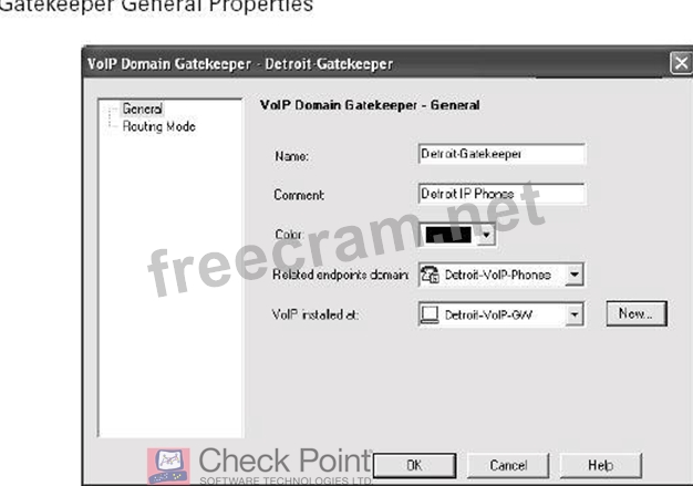
21-1
3.Under the Routing Mode tab of the gatekeeper properties, you can
choose from three allowed routing modes. This option identifies
which connections will be rerouted from your VoIP gatekeeper to the
VoIP gatekeeper on the other end. At least one of the following choices must be checked depending on the VoIP equipment that is being utilized:
DirectThe H.225 and Q.931 protocols, which allow gatekeeper to
gatekeeper communication and call setup and breakdown respectively,
are rerouted if this check box is selected.
Call Setup (Q.931)H.245 which is the control protocol used by H.323
for multimedia communication will be rerouted from gatekeeper to gatekeeper along with the Q.931 protocols.
Call Setup (Q.931) and Call Control (H.245)Connections that deal
with video, audio and controls connections associated with video and
audio will be rerouted gatekeeper to gatekeeper.
VoIP is a large set of protocols that are not easily understood. A good resource to learn more about VoIP ishttp://www.voip-calculator.com/.
Configuring Global Properties
In the VoIP page of the Global Properties window, shown in Figure below, you can change the VoIP parameters from their default settings. If the Log VoIP Connection option is checked, every VoIP (SIP and H.323) connection will be logged including the telephone number information. Under the H.323 section, Allow to Re-direct Connections is a H.323 function that allows call forwarding and call waiting to occur. Disallow Blank Source Phone Numbers is what we commonly know as blocking CallerID. Enable Dynamic T.120 enables the T.120 protocol which most recognize as the whiteboarding feature of NetMeeting.
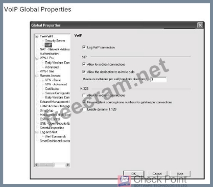
21-2
Configuring the Rule Base
Now that you have created your network objects and configured your VoIP global parameters, it's time to configure the rule base to filter H.323 traffic.
The concept in creating the rule is to allow traffic to pass from gatekeeper to gatekeeper or from gateway to gateway using the H.323 service. You have more than one H.323 service to choose from: H.323_any provides all the required services for VoIP, and H.323_ras includes only the RAS part of the
H.323 protocol. If you wish to use more than just H.323_ras then you will have to define additional services for this rule or create additional rules to allow the other protocols (e.g. T.120 orH.450) necessary for the call to be completed.
For our purposes in this book, Figure below displays a good example of an H.323 VoIP rule. The gatekeepers of Detroit and Madrid are listed in both the Source and Destination columns of the rule. The Service is H.323_any, and the Action is Accept.
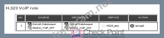
21-3
You now have an understanding of how to configure the firewall for
H.323-based VoIP systems. Now look at the next section where you will
learn how to configure SIP-based VoIP systems.
Analog (conventional) telephones and digital (soft) telephones can be used in conjunction with a H.323-based VoIP solution. Conventional phones do not have IP addresses but can be connected to a H.323 gateway which converts the analog signal to digital so that it can participate in VoIP. Digital phones can be either a physical telephone that has an IP address or a computer with the appropriate software that enables it to act as a telephone. Both of these configurations are referred to as "soft phones." The IP addresses of the gateway (if necessary) and the soft phones should be their own subnet along with the H.323 gatekeeper computer.
The gatekeeper H.323 component is the focal point for all calls within a VoIP network. It provides important services such as addressing, authorization, and authentication for the gateway and the IP phones behind it. The gatekeeper can also provide bandwidth management, accounting, billing, charging, and call-routing services.
The first step in configuring the firewall to inspect VoIP traffic is to define host node and/or network objects that represent the IP phones, the gateway computer (optional) and the gatekeeper computer. The gatekeeper and the gateway should be created as host objects. Each IP phone can be a host node object as well or you could create a network object that represents the IP address range of your VoIP network. The only portion of the H.323 architecture in which you do not have to create objects is the analog phones. Since they don't have IP addresses, they are represented by the gateway object. If you do not have analog phones then you have no need to create a gateway object.
Creating the Gateway
If you have analog phones in your VoIP network you must create a VoIP
Domain H.323 Gateway object as outlined in the following steps:
1.
Go to Manage _
Network Objects and choose New _
VoIP Domains _
VoIP Domain H.323 Gateway.
2.
In the General tab, define the gateway's Name, Comment, and Color.
Choose the network object that represents the IP addresses of your
VoIP subnet in the Related Endpoints Domain pull-down menu. Keep
in mind that if different H.323 protocols are carried on different interfaces, then a separate host node object has to be created to represent each interface. These host node objects should then be grouped together and defined in the VoIP Installed field. If there is a single interface carrying the protocols that make up H.323 then only one host node object (which represents the H.323 gateway) should be defined in the VoIP Installed At field.
3.
In the Routing Mode tab, you'll see two options: the Call Setup and
Call Setup And Call Control. Call Setup (Q.931) handles the setup and
termination of the calls whereas Call Setup And Call Control does that
as well as negotiating the parameters necessary for multimedia. At
least one of the choices must be checked, depending on the VoIP product that you are using.
Most people are not familiar with the H.323 protocol but have experienced using it if they've ever used Microsoft's NetMeeting product.
Creating the Gatekeeper
The gatekeeper object must be created to securely pass H.323 traffic through your firewall. To create a gatekeeper object, follow these steps:
1.
Go to Manage _
Network Objects Go to the Network Objects window
and choose New _
VoIP Domains _
VoIP Domain H.323 Gatekeeper.
2.In the General tab, shown in Figure below, define the gatekeeper's Name, Comment, and Color. The network object or address range object that represents your soft phones subnet and/or the object that represents your gateway (if you're using analog phones) should be defined in the Related Endpoints Domain field. If you are using a combination of analog and digital phones then combine the gateway and the network range in a Simple Group and define it here. The host node object that represents your H.323 gatekeeper machine should be defined in the VoIP Installed At field.
21-1
3.Under the Routing Mode tab of the gatekeeper properties, you can
choose from three allowed routing modes. This option identifies
which connections will be rerouted from your VoIP gatekeeper to the
VoIP gatekeeper on the other end. At least one of the following choices must be checked depending on the VoIP equipment that is being utilized:
DirectThe H.225 and Q.931 protocols, which allow gatekeeper to
gatekeeper communication and call setup and breakdown respectively,
are rerouted if this check box is selected.
Call Setup (Q.931)H.245 which is the control protocol used by H.323
for multimedia communication will be rerouted from gatekeeper to gatekeeper along with the Q.931 protocols.
Call Setup (Q.931) and Call Control (H.245)Connections that deal
with video, audio and controls connections associated with video and
audio will be rerouted gatekeeper to gatekeeper.
VoIP is a large set of protocols that are not easily understood. A good resource to learn more about VoIP ishttp://www.voip-calculator.com/.
Configuring Global Properties
In the VoIP page of the Global Properties window, shown in Figure below, you can change the VoIP parameters from their default settings. If the Log VoIP Connection option is checked, every VoIP (SIP and H.323) connection will be logged including the telephone number information. Under the H.323 section, Allow to Re-direct Connections is a H.323 function that allows call forwarding and call waiting to occur. Disallow Blank Source Phone Numbers is what we commonly know as blocking CallerID. Enable Dynamic T.120 enables the T.120 protocol which most recognize as the whiteboarding feature of NetMeeting.
21-2
Configuring the Rule Base
Now that you have created your network objects and configured your VoIP global parameters, it's time to configure the rule base to filter H.323 traffic.
The concept in creating the rule is to allow traffic to pass from gatekeeper to gatekeeper or from gateway to gateway using the H.323 service. You have more than one H.323 service to choose from: H.323_any provides all the required services for VoIP, and H.323_ras includes only the RAS part of the
H.323 protocol. If you wish to use more than just H.323_ras then you will have to define additional services for this rule or create additional rules to allow the other protocols (e.g. T.120 orH.450) necessary for the call to be completed.
For our purposes in this book, Figure below displays a good example of an H.323 VoIP rule. The gatekeepers of Detroit and Madrid are listed in both the Source and Destination columns of the rule. The Service is H.323_any, and the Action is Accept.
21-3
You now have an understanding of how to configure the firewall for
H.323-based VoIP systems. Now look at the next section where you will
learn how to configure SIP-based VoIP systems.


- Question List (187q)
- Question 1: What is the filename of the file on a SecuRemote client that...
- Question 2: Which of the following is NOT a function of the Internal Cer...
- Question 3: Content Vectoring Protocol (CVP), by default uses which TCP?...
- Question 4: Which phase of the IKE process uses a previously negotiated ...
- Question 5: Which of the following levels of encryption is used by finan...
- Question 6: Which load balancing algorithm allocates the server based on...
- Question 7: Which load balancing algorithm chooses the server closest to...
- Question 8: The Service drop-down menu in the OPSEC Definition Propertie...
- Question 9: Where would you select the load balancing server type for a ...
- Question 10: Which of the following encryption algorithms is a symmetric-...
- Question 11: Which VPN type is used by SecuRemote?...
- Question 12: When you first connect to a certificate authority you get a ...
- Question 13: Which programming language cannot be used for writing user d...
- Question 14: If the Persistent Server mode check box is selected in the L...
- Question 15: To reduce the effectiveness of traffic sniffing inside the L...
- Question 16: What are valid advantages of binding a Secure Client user id...
- Question 17: Which is NOT a valid parameter in the userc.C options sectio...
- Question 18: Which encryption algorithm as supported by VPN1/WF1 uses a k...
- Question 19: In the following graphic, the remote SecureClient machine do...
- Question 20: Exhibit (Exhibit) Dr Billwants to reduce encryption overhead...
- Question 21: Dr Billis his organization's Chief Technology Officer. He is...
- Question 22: When you connect to a site referenced in your database SecuR...
- Question 23: Which type of encryption encapsulates the entire packet incl...
- Question 24: In the event that an unauthorized user attempts to compromis...
- Question 25: Which form of overlapping encryption domain is NOT supported...
- Question 26: In the event that an unauthorized user attempts to compromis...
- Question 27: Put the following LDAP distinguished name entities in hierar...
- Question 28: Which of the following is a Checkpoint proprietary encryptio...
- Question 29: You are logging into a Policy Server in order to update or d...
- Question 30: What is the term given to a number of VPN-1/FW-1 gateways th...
- Question 31: A digital signature:
- Question 32: If a resource is specified in the Services field of a Rule B...
- Question 33: Which of the following is an encryption method that uses a d...
- Question 34: The "Man in the Middle" threat consists of the possibility o...
- Question 35: VPN-1/Firewall-1 gateway products (other than the GUI) are s...
- Question 36: MEP VPN's support both SecuRemote and Secure Client connecti...
- Question 37: Which of the following desktop policies can be modified by t...
- Question 38: Exhibit (Exhibit) In the exhibit, SecureClient can be used i...
- Question 39: Which is NOT a valid policy for a Secure Client desktop?...
- Question 40: What is true about proper subset encryption domains?...
- Question 41: Your Manager has requested that you implement a policy that ...
- Question 42: Which of the following statements best describe the purpose ...
- Question 43: In VPN-1/FireWall-1, Security Administrators can define URI ...
- Question 44: The Internal Certificate Authority (ICA) is installed on whi...
- Question 45: Which CPMAD attack is defined as a SYN packet with the sourc...
- Question 46: MD5 is the only data integrity method applicable to the FWZ ...
- Question 47: Which encryption schemes are supported by SecuRemote? (Choos...
- Question 48: By default where does VPN-1/Firewall-1 look for a user-defin...
- Question 49: You are a VPN-1/FireWall-1 Security Administrator. You must ...
- Question 50: What are the two types of login for a Secure Client user? (C...
- Question 51: When configuring an FTP resource for content security where ...
- Question 52: Respond to unauthenticated topology requests (IKE and FWI) o...
- Question 53: What happens if CPMAD runs out of memory?...
- Question 54: Which of the following CPMAD parameter types controls the am...
- Question 55: Which of the following is NOT a valid VPN configuration opti...
- Question 56: The Solaris command to install the Enforcement Module softwa...
- Question 57: For each connection that is established through a VPN-1/Fire...
- Question 58: Which commands would you use to stop and start Firewall1?...
- Question 59: When configuring match parameters for content security resou...
- Question 60: Dr Billis a Security Administrator preparing to configure hi...
- Question 61: What is the name given to the ability of a CVP manager to se...
- Question 62: Which encryptions schemes are supported by VPN1/FW1? (Choose...
- Question 63: Which two of the following CPMAD parameter types combine to ...
- Question 64: Secure Client only supports Microsoft TCP stacks. True or fa...
- Question 65: In a SEP VPN when a gateway fails, a backup will take its pl...
- Question 66: Which of the following uses an external certificate authorit...
- Question 67: A SecureClient configuration is being verified with Secure C...
- Question 68: Which of the following conditions will cause Secure Client V...
- Question 69: When upgrading a configuration to NG with Application Intell...
- Question 70: Which of the following happens if the userc.C syntax is inco...
- Question 71: What are the two modes for phase 1 of the ISAKMP scheme? (Ch...
- Question 72: If there are two gateways and two encryption domains which a...
- Question 73: What is the name given to a server giving anti virus protect...
- Question 74: The four policies that can be applied to a Secure Client des...
- Question 75: What version of VPN1/FW1 introduced Secure Client?...
- Question 76: Which of the following selections lists the three security c...
- Question 77: When configuring an ARP entry in an windows server running a...
- Question 78: How many certificates can one entity have from a single Cert...
- Question 79: If you have modified your network configuration by removing ...
- Question 80: Mark is preparing to install VPN-1/FireWall-1 and has create...
- Question 81: What is true about the Secure Client users ability to disabl...
- Question 82: Which product is NOT under the "mobile/desktop components" s...
- Question 83: When licensing a VPN-1/Firewall-1 Management Server, for cen...
- Question 84: Which form of overlapping encryption domain is described as ...
- Question 85: Choose three. The Check Point SecureClient Packaging Tool al...
- Question 86: The IKE encryption scheme encrypts the original TCP and IP h...
- Question 87: What is the name of the Secure Client facility that can crea...
- Question 88: You are importing a URI specification file from the Match ta...
- Question 89: Which of the following is NOT covered by FW1's content secur...
- Question 90: SYNDefender configuration is common to all gateways and host...
- Question 91: Having configured a content security resource how would you ...
- Question 92: What does LDAP stand for?
- Question 93: If you do not configure any groups during Solaris installati...
- Question 94: How would a Secure Client user log onto the policy server? (...
- Question 95: You are the VPN-1/Firewall-1 administrator for a company WAN...
- Question 96: When you select the Pre-Shared Secret check box in the IKE P...
- Question 97: Where would you configure a user defined alert command?...
- Question 98: Determine the appropriate routing mode for a Voice over IP (...
- Question 99: Which VPN-1/FireWall-1 Security Server does NOT perform auth...
- Question 100: If a web user has requested a URL that contains unsuitable m...
- Question 101: Asymmetric routing is when a return packet is not routed thr...
- Question 102: Which of the following is NOT a method used to configure SIP...
- Question 103: Where would you configure a pre-shared secret for the IKE sc...
- Question 104: The Check Point Secure Client packaging tool enables system ...
- Question 105: How many attack types can be monitored by CPMAD?...
- Question 106: SecuRemote requires the use of network driver interface spec...
- Question 107: Which of the following statements BEST describes the differe...
- Question 108: When a Secure Client user logs on the password is remembered...
- Question 109: SYNDefender Gateway sends a FIN/ACK packet in immediate resp...
- Question 110: What parameter in userc.C allows you to set the port for top...
- Question 111: In which tab of an SMTP definition screen would you specify ...
- Question 112: Secure Client adds a new pull down menu option to the SecuRe...
- Question 113: Which security server or service provides protection by: hid...
- Question 114: What is the correct protocol sequence when opening a TCP ses...
- Question 115: What is NOT true about single signon?...
- Question 116: When SecuRemote Client and Server key exchange occurs, the u...
- Question 117: When configuring a URI definition what is NOT a valid URI ma...
- Question 118: What is the default timeout value for SYNDefender to wait fo...
- Question 119: If you check the "cache static passwords on the desktop" opt...
- Question 120: Secure Client can use Reliable Datagram Protocol (RDP) statu...
- Question 121: Where is the default SMTP error-handling server configured?...
- Question 122: In a fully overlapping encryption domain with two gateways s...
- Question 123: Which security server or service provides protection by bloc...
- Question 124: Which of the following is NOT true about a SEP VPN?...
- Question 125: What are the disadvantages of Shared Secret Key encryption?...
- Question 126: How would you configure a SEP VPN from the global properties...
- Question 127: Which encryption algorithms are supported by IKE? (Choose al...
- Question 128: Some VPN-1/Firewall-1 tracking options generate log entries ...
- Question 129: When using an "other" load balancing server type it uses NAT...
- Question 130: Which of the following FTP Content Security settings prevent...
- Question 131: What is NOT true if you add a SecuRemote site and its encryp...
- Question 132: In the following graphic, the remote Secure Client machine d...
- Question 133: Which of the following statements BEST explains the differen...
- Question 134: Dr Billis assisting a SecureClient user who is not able to a...
- Question 135: Which of the following is NOT a CPMAD global configuration p...
- Question 136: When using FW1 load balancing where does the logical server ...
- Question 137: What is NOT true about a SEP VPN?...
- Question 138: The following URL specification blocks access to the /warez/...
- Question 139: Which operating system can NG FW1 NOT be used under? (Choose...
- Question 140: Dr Billis a Security Administrator for a financial firm with...
- Question 141: Which of the following protocols open back connections on an...
- Question 142: TCP services must have a rule in the Policy Editor Rule Base...
- Question 143: Diffie-Hellman uses which type of key exchange?...
- Question 144: How do determine what version of firewall kernel a customer ...
- Question 145: Which of the following statements is FALSE?...
- Question 146: Which of the following statements is FALSE concerning Policy...
- Question 147: The encryption key for SecuRemote connections, for two phase...
- Question 148: Which is NOT a valid term used in relation to the IKE encryp...
- Question 149: Which encryption algorithms are supported by FWZ? (Choose al...
- Question 150: If you wanted to use content security on an SMTP resource wh...
- Question 151: What is the name of the FW1 facility that scans the log file...
- Question 152: If the Use Aggressive Mode check box in the IKE Properties d...
- Question 153: SecuRemote operates between the _______and the ______....
- Question 154: SYN flood attacks are used in the Denial-of-Service (Dos) at...
- Question 155: Which is NOT a valid content security function under the HTM...
- Question 156: What is the default name for a user defined script or progra...
- Question 157: What is the name given to a globally unique entity within an...
- Question 158: When you upgrade VPN-1/FireWall-1, what components are carri...
- Question 159: How would you apply encryption to a rule?...
- Question 160: What is the purpose of HTML weeding when a defining a URI re...
- Question 161: What is NOT true about in-place encryption?...
- Question 162: Ann would like to deploy H.323 with a gatekeeper and gateway...
- Question 163: A load balancing logical server does not really exist theref...
- Question 164: Which of the following does NOT require definition for a Voi...
- Question 165: Exhibit (Exhibit) Dr Billis adjusting the Global Properties ...
- Question 166: Dr Billis a Security Administrator configuring SecuRemote as...
- Question 167: VPN-1/FireWall-1 allows a Security Administrator to define f...
- Question 168: When a SecuRemote Client and Server key exchange occurs, the...
- Question 169: What is NOT true about the FWZ-1 encryption algorithm?...
- Question 170: What are the two types of HTTP Security Server authenticatio...
- Question 171: What parameters are available on the SYNDefender screen of g...
- Question 172: Which load balancing algorithm uses pings to determine the b...
- Question 173: What is the name given to a denial of service attack that co...
- Question 174: Which options are NOT available on the personal tab when con...
- Question 175: Exhibit (Exhibit) Dr Billis senior Security Administrator wh...
- Question 176: Which command is used to export a group of users from VPN-1/...
- Question 177: The userc.C file contains information for SecuRemote and Sec...
- Question 178: When adding users to firewall, an administrator can install ...
- Question 179: What is AMC used for?
- Question 180: Which of the following is TRUE of the relationship between t...
- Question 181: Which of the following statements, about Hybrid Ike, are FAL...
- Question 182: Dr Billwants to configure a custom script to launch an appli...
- Question 183: What is the VPN type that is between two firewalls?...
- Question 184: There are certain general recommendations for improving the ...
- Question 185: If there is NAT in the path of a Secure Client connection it...
- Question 186: Which of the following levels of encryption supports a key l...
- Question 187: You must configure your firewall for Hybrid IKE Secure Clien...
