- Home
- Cisco
- Implementing Cisco Enterprise Network Core Technologies (350-401 ENCOR)
- Cisco.350-401.v2025-04-02.q599
- Question 74
Valid 350-401 Dumps shared by ExamDiscuss.com for Helping Passing 350-401 Exam! ExamDiscuss.com now offer the newest 350-401 exam dumps, the ExamDiscuss.com 350-401 exam questions have been updated and answers have been corrected get the newest ExamDiscuss.com 350-401 dumps with Test Engine here:
Access 350-401 Dumps Premium Version
(382 Q&As Dumps, 35%OFF Special Discount Code: freecram)
<< Prev Question Next Question >>
Question 74/599
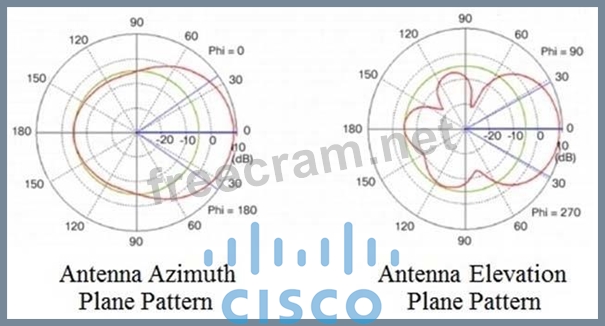
Refer to the exhibit. Which type of antenna do the radiation patterns present?
Correct Answer: A
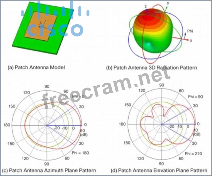
A patch antenna, in its simplest form, is just a single rectangular (or circular) conductive plate that is spaced above a ground plane. Patch antennas are attractive due to their low profile and ease of fabrication.
The azimuth and elevation plane patterns are derived by simply slicing through the 3D radiation pattern. In this case, the azimuth plane pattern is obtained by slicing through the x-z plane, and the elevation plane pattern is formed by slicing through the y-z plane. Note that there is one main lobe that is radiated out from the front of the antenna. There are three back lobes in the elevation plane (in this case), the strongest of which happens to be 180 degrees behind the peak of the main lobe, establishing the front-to-back ratio at about 14 dB. That is, the gain of the antenna 180 degrees behind the peak is 14 dB lower than the peak gain.
Again, it doesn't matter if these patterns are shown pointing up, down, to the left or to the right.
That is usually an artifact of the measurement system. A patch antenna radiates its energy out from the front of the antenna. That will establish the true direction of the patterns.
Reference: https://www.cisco.com/c/en/us/products/collateral/wireless/aironet-antennas- accessories/prod_white_paper0900aecd806a1a3e.html


- Question List (599q)
- Question 1: How are control traffic, client authentication and data traf...
- Question 2: Refer to the exhibit. A network operator is attempting to co...
- Question 3: Drag and Drop Question Drag and drop the solutions that comp...
- Question 4: Lab Simulation 22 Guidelines This is a lab item in which tas...
- Question 5: Which method is used by an AP to join HA controllers and is ...
- Question 6: An engineer must construct an access list for a Cisco Cataly...
- Question 7: Which feature Is used to propagate ARP broadcast, and link-l...
- Question 8: Which capability does a distributed virtual switch have?...
- Question 9: A network engineer must configure a switch to allow remote a...
- Question 10: Refer to the exhibit. The OSPF neighborship fails between tw...
- Question 11: Drag and Drop Question Please drag and drop the options prov...
- Question 12: Drag and Drop Question An engineer must create a script to a...
- Question 13: What is one method for achieving REST API security?...
- Question 14: What are two reasons to define static peers in EIGRP? (Choos...
- Question 15: Which two components are supported by LISP? (choose two )...
- Question 16: Drag and Drop Question Drag and drop the characteristics fro...
- Question 17: Which two methods are used to interconnect two Cisco SD-Acce...
- Question 18: Which component transports data plane traffic across a Cisco...
- Question 19: Drag and Drop Question Drag and drop the characteristics fro...
- Question 20: Which tunnel type allows clients to perform a seamless Layer...
- Question 21: How do cloud deployments compare to on-premises deployments?...
- Question 22: Refer to the exhibit. Which configuration enables fallback t...
- Question 23: Which statement about Type-4 LSA in OSPFv2 is true?...
- Question 24: Which two steps are required for a complete Cisco DNA Center...
- Question 25: Lab Simulation 35 Guidelines This is a lab item in which tas...
- Question 26: An engineer measures the Wi-Fi coverage at a customer site T...
- Question 27: What are the two variants of NTPv4? (Choose two.)...
- Question 28: In a Cisco SD-Access fabric architecture, which of the follo...
- Question 29: In Cisco DNA Center, what is the integration API?...
- Question 30: Lab Simulation 11 Guidelines This is a lab item in which tas...
- Question 31: Refer to the exhibit. What is the JSON syntax that is formed...
- Question 32: What does the destination MAC on the outer MAC header identi...
- Question 33: Lab Simulation 38 Guidelines This is a lab item in which tas...
- Question 34: Refer to the exhibit. An engineer must assign an IP address ...
- Question 35: Refer to the exhibit. Which configuration change ensures tha...
- Question 36: A company hires a network architect to design a new OTT wire...
- Question 37: A network engineer configures a WLAN controller with increas...
- Question 38: What is the function of Cisco DNA Center in a Cisco SD-Acces...
- Question 39: Drag and Drop Question Drag and drop the characteristics fro...
- Question 40: Refer to the exhibit. An engineer must configure an ERSPAN t...
- Question 41: When the "deny" statement is used within a route map that is...
- Question 42: Refer to the exhibit. A network engineer troubleshoots an is...
- Question 43: Router1 is currently operating as the HSRP primary with a pr...
- Question 44: Refer to the exhibit. Which statement about the OPSF debug o...
- Question 45: Which two statements about marking fields are true? (Choose ...
- Question 46: Refer to the exhibit. Which GRE tunnel configuration command...
- Question 47: Witch two actions provide controlled Layer 2 network connect...
- Question 48: Drag and Drop Question Drag and drop the characteristics fro...
- Question 49: Which component of TCP defines the maximum packet size that ...
- Question 50: Which function does a Cisco SD-Access extended node perform?...
- Question 51: Which statement about dynamic GRE between a headend router a...
- Question 52: Refer to the exhibit. An administrator troubleshoots intermi...
- Question 53: Which Cisco Locator/ID Separation Protocol (LISP) device rec...
- Question 54: Which function is performed by vSmart in the Cisco SD-WAN ar...
- Question 55: Which command set configures RSPAN to capture outgoing traff...
- Question 56: Which devices does Cisco DNA Center configure when deploying...
- Question 57: What is one fact about Cisco SD-Access wireless network depl...
- Question 58: Drag and Drop Question Drag and drop the characteristics fro...
- Question 59: Refer to the exhibit. An administrator must collect basic st...
- Question 60: Which two statements about IPv4 and IPv6 networks are true? ...
- Question 61: What is the function of a control-plane node in a Cisco SD-A...
- Question 62: Which feature is supported by EIGRP but is not supported by ...
- Question 63: Refer to the exhibit. An engineer must configure router R1 t...
- Question 64: What is an emulated machine that has dedicated compute, memo...
- Question 65: Which two statements about the STP dispute function are true...
- Question 66: Refer to the exhibit. These commands have been added to the ...
- Question 67: What is one difference between saltstack and ansible?...
- Question 68: Drag and Drop Question A network engineer is adding an addit...
- Question 69: Which statement about TLS is true when using RESTCONF to wri...
- Question 70: What does the Cisco DNA Center Authentication API provide?...
- Question 71: Lab Simulation 10 Guidelines This is a lab item in which tas...
- Question 72: Refer to the exhibit. An engineer troubleshoots connectivity...
- Question 73: Which two LISP infrastructure elements are needed to support...
- Question 74: Refer to the exhibit. Which type of antenna do the radiation...
- Question 75: A client device roams between wireless LAN controllers that ...
- Question 76: Which hypervisor requires a host OS to run and is not allowe...
- Question 77: Which two statements about EIGRP load balancing are true? (C...
- Question 78: Drag and Drop Question Drag and drop the code snippets from ...
- Question 79: Refer to the exhibit. Which set of commands is required to c...
- Question 80: Drag and Drop Question An engineer plans to use Python to co...
- Question 81: Which component of the Cisco Cyber Threat Defense solution p...
- Question 82: What is one primary REST security design principle?...
- Question 83: What is the difference between the MAC address table and TCA...
- Question 84: Which security feature does stateless authentication and aut...
- Question 85: What is a benefit of deploying an on-premises infrastructure...
- Question 86: Refer to the exhibit. Which privilege level is assigned to V...
- Question 87: Which two statements about 6to4 tunnels are true? (Choose tw...
- Question 88: In cisco SD_WAN, which protocol is used to measure link qual...
- Question 89: Refer to the exhibit. R2 is mutually redistributing between ...
- Question 90: A new multicast server is being added to an existing PIM Spa...
- Question 91: In a Cisco SD-Access solution, which protocol is used by an ...
- Question 92: Which data plane protocol does EIGRP Over the Top use?...
- Question 93: What is a characteristic of Cisco DNA Northbound APIs?...
- Question 94: Refer to the following two images regarding QoS Traffic Shap...
- Question 95: Based on this interface configuration, what is the expected ...
- Question 96: What is the purpose of data modeling languages?...
- Question 97: Refer to the exhibit. An engineer configures the trunk and p...
- Question 98: Which three options are the main security features in SNMPv3...
- Question 99: Refer to the exhibit. An engineer attempts to use RESTCONF t...
- Question 100: A vulnerability assessment highlighted that remote access to...
- Question 101: Which feature is supported by ElGRP but is not supported by ...
- Question 102: Which two items are found in YANG data models? (Choose two.)...
- Question 103: Refer to the exhibit. A network engineer configures OSPF and...
- Question 104: Refer to the exhibit. Which LISP component do routers in the...
- Question 105: Drag and Drop Question An engineer is working with the Cisco...
- Question 106: An engineer must configure HSRP for VLAN 1200 on SW1. The se...
- Question 107: Refer to the exhibit. Extended access-list 100 is configured...
- Question 108: In the Cisco DNA Center Image Repository, what is a golden i...
- Question 109: Which variable in an EEM applet is set when you use the sync...
- Question 110: What is the recommended minimum SNR for Voice applications f...
- Question 111: Drag and Drop Question Drag and drop the snippets onto the b...
- Question 112: Refer to the exhibit. What happens to access interfaces wher...
- Question 113: What is the purpose of an RP in PIM?...
- Question 114: Which three features are supported by PIMv6? (Choose three)...
- Question 115: Which feature is offered by the Cisco Advanced Malware Prote...
- Question 116: An engineer is configuring Local WebAuth on a Cisco Wireless...
- Question 117: Where is radio resource management performed in a cisco SD-a...
- Question 118: Refer to the exhibit. An engineer configures HSRP and enters...
- Question 119: What are two benefits of using Cisco TrustSec? (Choose two.)...
- Question 120: A response code of 404 is received while using the REST API ...
- Question 121: Refer to the exhibit. An engineer configures routing between...
- Question 122: By default, which virtual MAC address does HSRP group 14 use...
- Question 123: What is the correct EBGP path attribute list, ordered from m...
- Question 124: In a Cisco DNA Center Plug and Play environment, why would a...
- Question 125: Based on the output below, which Python code shows the value...
- Question 126: Drag and Drop Question Drag and drop the characteristics fro...
- Question 127: Which statement must be used to export the contents of the d...
- Question 128: Drag and Drop Question Drag and drop the Cisco SD-Access sol...
- Question 129: What does the LAP send when multiple WLCs respond to the CIS...
- Question 130: When reason could cause an OSPF neighborship to be in the EX...
- Question 131: Company policy restricts VLAN 10 to be allowed only on SW1 a...
- Question 132: Refer to the exhibit. What does the snippet of code achieve?...
- Question 133: Drag and Drop Question Drag and drop the characteristics fro...
- Question 134: Under which network conditions is an outbound QoS policy tha...
- Question 135: Drag and Drop Question Drag and drop the characteristics fro...
- Question 136: Which VXLAN component is used to encapsulate and decapsulate...
- Question 137: Two Cisco switches are logically configured as a single swit...
- Question 138: Refer to the exhibit. A network engineer must block Telnet t...
- Question 139: Refer to the exhibit. R2 is the neighboring router of R1. R2...
- Question 140: Which marking field is used only as an internal marking with...
- Question 141: A company requires a wireless solution to support its main o...
- Question 142: Refer to the exhibit. Which command set must be applied on R...
- Question 143: Which statement is true about PIM?...
- Question 144: Which mechanism can be used to enforce network access authen...
- Question 145: How is CAPWAP data traffic encapsulated when running an Over...
- Question 146: An engineer must configure the strongest password authentica...
- Question 147: How do stratum levels relate to the distance from a time sou...
- Question 148: What does Call Admission Control require the client to send ...
- Question 149: AN engineer is implementing a route map to support redistrib...
- Question 150: Which device makes the decision for a wireless client to roa...
- Question 151: Refer to the exhibit. Two indirectly connected routers fail ...
- Question 152: What is one characteristic of Cisco DNA Center and vManage n...
- Question 153: An engineer must enable a login authentication method that a...
- Question 154: Which measure is used by an NTP server to indicate its close...
- Question 155: Which configuration enables a device to be configured via NE...
- Question 156: Refer to the exhibit. An engineer attempts to configure a tr...
- Question 157: How does EIGRP differ from OSPF?...
- Question 158: A network engineer wants to configure console access to a ro...
- Question 159: Which two methods are used to reduce the AP coverage area? (...
- Question 160: Which Cisco WLC feature allows a wireless device to perform ...
- Question 161: Which two statements about AAA authentication are true? (Cho...
- Question 162: How is OAuth framework used in REST API?...
- Question 163: During deployment, a network engineer notices that voice tra...
- Question 164: Which feature of EIGRP is not supported in OSPF?...
- Question 165: Which Python code snippet must be added to the script to sto...
- Question 166: Which new enhancement was implemented in Wi-Fi 6?...
- Question 167: Which encryption hashing algorithm does NTP use for authenti...
- Question 168: Drag and Drop Question Drag and drop the snippets onto the b...
- Question 169: Which wireless deployment mode uses a Flex architecture and ...
- Question 170: When should the MAC authentication bypass feature be used on...
- Question 171: After a redundant route processor failure occurs on a Layer ...
- Question 172: Refer to the exhibit. Which configuration must be applied fo...
- Question 173: Drag and Drop Question Drag and drop the characteristics fro...
- Question 174: Which access control feature does MAB provide?...
- Question 175: Which two statements about OSPF are true? (Choose two.)...
- Question 176: What are two characteristics of vManage APIs? (Choose two.)...
- Question 177: Which three statements about OSPFv3 address families are tru...
- Question 178: A customer requests a design that includes GLBP as the FHRP....
- Question 179: Refer to the exhibit. What is the output of this code? (Exhi...
- Question 180: Which two advanced security features are available in next-g...
- Question 181: Refer to the exhibit. An engineer is troubleshooting an issu...
- Question 182: Which JSON script is properly formatted?...
- Question 183: Refer to the exhibit. What is the value of the variable list...
- Question 184: Which NGFW mode blocks flows crossing the firewall?...
- Question 185: Drag and Drop Question Drag and drop the characteristics fro...
- Question 186: Which technology provides an overlay fabric to connect remot...
- Question 187: When is the Design workflow used In Cisco DNA Center?...
- Question 188: What are two differences between the RIB and the FIB? (Choos...
- Question 189: Which two conditions occur when the primary route processor ...
- Question 190: When a wireless client roams between two different wireless ...
- Question 191: Which type of ACL can be applied only to Layer 2 pods?...
- Question 192: Which controller is the single plane of management for Cisco...
- Question 193: Refer to the exhibit. Which IP address becomes the next acti...
- Question 194: Refer to the exhibit. Which action must be taken to configur...
- Question 195: While configuring an IOS router for HSRP with a virtual IP o...
- Question 196: In a Cisco SD-Access solution, what is the role of the Ident...
- Question 197: Drag and Drop Question Drag and drop the automation characte...
- Question 198: Drag and Drop Question Drag and drop the Qos mechanisms from...
- Question 199: Refer to the exhibit. An engineer must ensure that all traff...
- Question 200: What are two reasons why broadcast radiation is caused in th...
- Question 201: Drag and Drop Question Drag and drop the tools from the left...
- Question 202: By default, which virtual MAC address does HSRP group 16 use...
- Question 203: Which authorization framework gives third-party applications...
- Question 204: When is it useful to disable split horizon on an EIGRP inter...
- Question 205: What is the function of cisco DNA center in a cisco SD-acces...
- Question 206: A customer has completed the installation of a Wi-Fi 6 green...
- Question 207: Which two operations are valid for RESTCONF? (Choose two.)...
- Question 208: Where are operations related to software images located in t...
- Question 209: Refer to the exhibit. Which two configurations enable R1 and...
- Question 210: Refer to the exhibit. An engineer implemented several config...
- Question 211: Refer to the exhibit. An engineer must permit traffic from t...
- Question 212: Which two entities are Type 1 hypervisors? (Choose two.)...
- Question 213: Which two new security capabilities are introduced by using ...
- Question 214: What is the function of a VTEP in VXLAN?...
- Question 215: What is the role of vSmart in a Cisco SD-WAN environment?...
- Question 216: Which method of account authentication does OAuth 2.0 use wi...
- Question 217: Refer to the exhibit. An engineer deploys a script to retrie...
- Question 218: Which TCP setting is tuned to minimize the risk of fragmenta...
- Question 219: Drag and Drop Question Drag and drop the characteristics fro...
- Question 220: Lab Simulation 18 Guidelines This is a lab item in which tas...
- Question 221: Refer to the exhibit. An engineer builds an EEM script to ap...
- Question 222: An engineer configures a WLAN with fast transition enabled. ...
- Question 223: A customer wants to connect a device to an autonomous Cisco ...
- Question 224: Refer to the exhibit. What is achieved by this Python script...
- Question 225: Lab Simulation 1 Guidelines This is a lab item in which task...
- Question 226: Which two options are required parts of an EEM policy? (Choo...
- Question 227: Which Python snippet should be used to store the devices dat...
- Question 228: What is one benefit of implementing a VSS architecture?...
- Question 229: What is the rose of the vSmart controller in a Cisco SD-WN e...
- Question 230: Which IP SLA operation requires the IP SLA responder to be c...
- Question 231: Which security measure mitigates a man-in-the-middle attack ...
- Question 232: Which Cisco FlexConnect state allows wireless users that are...
- Question 233: Lab Simulation 20 Guidelines This is a lab item in which tas...
- Question 234: When does a stack master lose its role?...
- Question 235: How does an IPv6 host automatically generate a global addres...
- Question 236: In which two ways does TCAM differ from CAM? (Choose two.)...
- Question 237: What is one difference between SaltStack and Ansible?...
- Question 238: An engineer must configure a new WLAN that allows a user to ...
- Question 239: Which exhibit displays a valid JSON file?...
- Question 240: According to the networking best practices, which network de...
- Question 241: An engineer is implementing a Cisco MPLS TE tunnel to improv...
- Question 242: Which design principle slates that a user has no access by d...
- Question 243: Drag and Drop Question Drag and drop the definitions in the ...
- Question 244: Lab Simulation 2 Guidelines This is a lab item in which task...
- Question 245: Which feature allows clients to perform Layer 2 roaming betw...
- Question 246: What is a characteristic of para-virtualization?...
- Question 247: In a Cisco SD-Access environment, which function is performe...
- Question 248: Which benefit is provided by the Cisco DNA Center telemetry ...
- Question 249: Refer to the exhibit. An engineer configured TACACS+ to auth...
- Question 250: Which statement about LISP encapsulation in an EIGRP OTP imp...
- Question 251: Refer to the exhibit. Which command set must be added to per...
- Question 252: Which two statements are true about control plane policing? ...
- Question 253: An engineer must configure a ACL that permits packets which ...
- Question 254: Lab Simulation 27 Guidelines This is a lab item in which tas...
- Question 255: Refer to the exhibit. An engineer must modify the access con...
- Question 256: Which two functions is an edge node responsible for? (Choose...
- Question 257: Drag and Drop Question Drag and drop the characteristics fro...
- Question 258: Refer to the Exhibit. An engineer is installing a new pair o...
- Question 259: Drag and Drop Question Drag and drop the definitions on the ...
- Question 260: Which Cisco SD-WAN component authenticates the routers and t...
- Question 261: Refer to the exhibit. interface Ethernet 0/0 ip policy route...
- Question 262: You want to create a policy that allows all TCP traffic in t...
- Question 263: By default, which virtual MAC address does HSRP group 12 use...
- Question 264: Which three elements determine Air Time efficiency? (Choose ...
- Question 265: Refer to the exhibit. Which command is required to verify NE...
- Question 266: Refer to the exhibit. Which outcome is achieved with this Py...
- Question 267: The Gig0/0 interface of two routers is directly connected wi...
- Question 268: Refer to the exhibit. Which action does the Python script ac...
- Question 269: Which JSON script is properly formatted?...
- Question 270: Which trunking configuration between two Cisco switches can ...
- Question 271: Refer to the exhibit. What is printed to the console when th...
- Question 272: Refer to the exhibit. Which action results from executing th...
- Question 273: Which solution do laaS service providers use to extend a Lay...
- Question 274: Refer to the exhibit. What are two effects of this configura...
- Question 275: Which device, in a LISP routing architecture, receives and d...
- Question 276: which features does Cisco EDR use to provide threat detectio...
- Question 277: Which statement about Cisco EAP-FAST is true?...
- Question 278: Drag and Drop Question Drag and drop the components of the C...
- Question 279: An engineer has deployed a single Cisco 5520 WLC with a mana...
- Question 280: By default, which virtual MAC address does HSRP group 32 use...
- Question 281: You need to implement a First Hop Redundancy Protocol (FHRP)...
- Question 282: When configuration WPA2 Enterprise on a WLAN, which addition...
- Question 283: Refer to the exhibit. Which two commands ensure that DSW1 be...
- Question 284: If a client's radio device receives a signal strength of -67...
- Question 285: A customer has several small branches and wants to deploy a ...
- Question 286: What is a characteristic of a type 2 hypervisor?...
- Question 287: Refer to the exhibit. An engineer is designing a guest porta...
- Question 288: Refer to the exhibit. Which configuration must be applied to...
- Question 289: Which IPv6 migration method relies on dynamic tunnels that u...
- Question 290: Which IEEE standard provides the capability to permit or den...
- Question 291: Refer to the exhibit. This is the configuration of the ASBR ...
- Question 292: Refer to the exhibit, Communication between London and New Y...
- Question 293: Which two sources cause interference for Wi-Fi networks? (Ch...
- Question 294: How do the MAC address table and TCAM differ?...
- Question 295: Refer to the exhibit. An engineer must create a script that ...
- Question 296: Which design principle should be followed in a Cisco SD-Acce...
- Question 297: What is the result of applying this access control list? ip ...
- Question 298: What is the main function of VRF-lite?...
- Question 299: Which mechanism can be used to enforce network access authen...
- Question 300: Which statement about VRRP is true?...
- Question 301: Refer to the exhibit. An engineer must reduce the number of ...
- Question 302: To authenticate with Cisco's DNA Center, which type of HTTP ...
- Question 303: Which OSPF networks types are compatible and allow communica...
- Question 304: Drag and Drop Question Drag and drop the automation characte...
- Question 305: A network is being migrated from IPV4 to IPV6 using a dual-s...
- Question 306: Refer to the exhibit. Which result does the python code achi...
- Question 307: Refer to the exhibit. What is the effect of these commands o...
- Question 308: Which protocol is implemented to establish secure control pl...
- Question 309: Which two methods are used to assign security group tags to ...
- Question 310: What are two device roles in Cisco SD-Access fabric? (Choose...
- Question 311: Which feature is provided by Cisco Mobility Services Engine ...
- Question 312: Refer to the exhibit. Which command filters the ERSPAN sessi...
- Question 313: Refer to the exhibit. An engineer attempts to create a confi...
- Question 314: Refer to the exhibit. Which EEM script generates a critical-...
- Question 315: Lab Simulation 5 Guidelines This is a lab item in which task...
- Question 316: Which method requires a client to authenticate and has the c...
- Question 317: What are some of the key differences between HSRPv1 and HSRP...
- Question 318: What is one difference between EIGRP and OSPF?...
- Question 319: A large campus network has deployed two wireless LAN control...
- Question 320: An engineer must configure a router to leak routes between t...
- Question 321: Refer to the exhibit. An engineer attempts to configure stan...
- Question 322: Which function does a fabric AP perform in a Cisco SD-Access...
- Question 323: Which type of antenna is designed to provide a 360-degree ra...
- Question 324: In a Cisco SD-Access network architecture, what is the role ...
- Question 325: Which HHTP status code is the correct response for a request...
- Question 326: A script contains the statement "while loop != 999:" Which v...
- Question 327: Which characteristic applies to a traditional WAN solution b...
- Question 328: What is one role of the VTEP in a VXLAN environment?...
- Question 329: Which characteristic applies to the endpoint security aspect...
- Question 330: An engineer is describing QoS to a client. Which two facts a...
- Question 331: Which First Hop Redundancy Protocol maximizes uplink utiliza...
- Question 332: Which Cisco DNA Center Assurance feature verifies host reach...
- Question 333: Lab Simulation 12 Guidelines This is a lab item in which tas...
- Question 334: Refer to the exhibit. An engineer must configure HSRP for VL...
- Question 335: A client device roams between access points located on diffe...
- Question 336: What are two benefits of implementing a Cisco SD-WAN archite...
- Question 337: If the noise floor is -90 dBm and wireless client is receivi...
- Question 338: Refer to the exhibit. An engineer is troubleshooting a conne...
- Question 339: Refer to the exhibit. An attacker can advertise OSPF fake ro...
- Question 340: Lab Simulation 4 Guidelines This is a lab item in which task...
- Question 341: How are map-register messages sent in a LISP deployment?...
- Question 342: How is traffic classified when using Cisco TrustSec technolo...
- Question 343: What is a characteristics of a vSwitch?...
- Question 344: Refer to the exhibit. Clients report that they cannot connec...
- Question 345: A network administrator applies the following configuration ...
- Question 346: An engineer is configuring a new SSID to present users with ...
- Question 347: Wireless users report frequent disconnections from the wirel...
- Question 348: Refer to the exhibit. What does the error message relay to t...
- Question 349: An engineer must configure a new WLAN that supports 802.11r ...
- Question 350: Refer to the exhibit. What is the result when a technician a...
- Question 351: Which of the following are valid statements when configuring...
- Question 352: Which line must be added in the Python function to return th...
- Question 353: Refer to the exhibit. Which command must be applied to Route...
- Question 354: Refer to the exhibit. Which configuration is required to sum...
- Question 355: Refer to the exhibit. The trunk does not work over the back-...
- Question 356: Independent, multiple OSPF processes are entered on the same...
- Question 357: Refer to the exhibit. Which result is achieved by the CoPP c...
- Question 358: Drag and Drop Question Drag and drop the descriptions of the...
- Question 359: Which action is a function of VTEP in VXLAN?...
- Question 360: Refer to the exhibit. What can be determined from the output...
- Question 361: Drag and Drop Question Drag and drop the characteristics fro...
- Question 362: A customer has a wireless network deployed within a multi-te...
- Question 363: Refer to the exhibit. An engineer must protect the CPU of th...
- Question 364: Lab Simulation 24 Guidelines This is a lab item in which tas...
- Question 365: Refer to the exhibit. Which action must be performed to allo...
- Question 366: Which JSON script is properly formatted?...
- Question 367: Which of the following statements regarding BFD are correct?...
- Question 368: Refer to the exhibit. Which action automatically enables pri...
- Question 369: Which network devices secure API platforms?...
- Question 370: The Overlay Management Protocol (OMP) is used as the control...
- Question 371: Which technology is used to provide Layer 2 and Layer 3 logi...
- Question 372: Which collection contains the resources to obtain a list of ...
- Question 373: Refer to the exhibit. An engineer attempts to bundle interfa...
- Question 374: Why would an engineer use YANG?...
- Question 375: What is the responsibility of a secondary WLC?...
- Question 376: Which device is responsible for finding EID-to-RLOC mapping ...
- Question 377: An engineer is configuring local web authentication on a WLA...
- Question 378: Refer to the exhibit. An administrator must enable RESTCONF ...
- Question 379: An engineer configures monitoring on SW1 and enters the show...
- Question 380: Which JSON syntax is valid?
- Question 381: Refer to the exhibit. A network engineer configures NAT on R...
- Question 382: Refer to the exhibit. Which action resolves the EtherChannel...
- Question 383: What is a characteristic of a virtual machine?...
- Question 384: PC 2 cannot communicate with PC 4. Which configuration resol...
- Question 385: A local router shows an EBGP neighbor in the Active state. W...
- Question 386: Refer to Exhibit. MTU has been configured on the underlying ...
- Question 387: An engineer configures GigabitEthernet 0/1 for VRRP group 11...
- Question 388: Which QoS mechanism is used to implement CoPP?...
- Question 389: Which NTP mode must be activated when using a Cisco router a...
- Question 390: Which configuration saves the running configuration to the s...
- Question 391: Which two methods are used by an AP that is typing to discov...
- Question 392: What is the wireless received signal strength indicator?...
- Question 393: Which NTP concept is used to measure the distance from a dev...
- Question 394: What does the number in an NTP stratum level represent?...
- Question 395: Which algorithms are used to secure REST API from brute atta...
- Question 396: Refer to the exhibit. An engineer configures OSPF and wants ...
- Question 397: Refer to the exhibit. Which troubleshooting a routing issue,...
- Question 398: What is used to perform QoS packet classification?...
- Question 399: Where in Cisco DNA Center is documentation of each API call,...
- Question 400: Which policy feature is used with TrustSec to provide endpoi...
- Question 401: In a Cisco VXLAN based network, which of the following best ...
- Question 402: The Radio Resource Management software that is embedded in t...
- Question 403: Which statement about TLS is accurate when using RESTCONF to...
- Question 404: An engineer must configure interface and sensor monitoring o...
- Question 405: Refer to the exhibit. An engineer must deny Telnet traffic f...
- Question 406: Refer to the exhibit. An engineer is investigating why guest...
- Question 407: What are two benefits of virtual switching when compared to ...
- Question 408: Drag and Drop Question Drag and drop the QoS mechanisms from...
- Question 409: Drag and Drop Question Drag and drop the characteristics fro...
- Question 410: What occurs when a high bandwidth multicast stream is sent o...
- Question 411: An engineer must configure interface GigabitEthernet0/0 for ...
- Question 412: Refer to the exhibit. How was spanning-tree configured on th...
- Question 413: What do Cisco DNA southbound APIs provide?...
- Question 414: Which component does Cisco Threat Defense use to measure ban...
- Question 415: Refer to the exhibit. What is generated by the script? (Exhi...
- Question 416: When using BFD in a network design, which consideration must...
- Question 417: Which time protocol offers security features and utilizes si...
- Question 418: An engineer must provide wireless converge in a square offic...
- Question 419: Lab Simulation 14 Guidelines This is a lab item in which tas...
- Question 420: What is the benefit of using TCAM for IP forwarding decision...
- Question 421: Which configuration restricts the amount of SSH traffic that...
- Question 422: Remote users cannot access the Internet but can upload files...
- Question 423: What is the recommended minimum SNR for data applications on...
- Question 424: What does the statement print(format(0.8, '.0%')) display?...
- Question 425: Refer to the exhibit. Which command set completes the ERSPAN...
- Question 426: How does the EIGRP metric differ from the OSPF metric?...
- Question 427: Refer to the exhibit. Which type of antenna does the radiati...
- Question 428: Which TLV value must be added to Option 43 when DHCP is used...
- Question 429: Refer to the exhibit. An engineer tries to log in to router ...
- Question 430: An engineer uses the Design workflow to create a new network...
- Question 431: A company plans to implement intent-based networking in its ...
- Question 432: Which two southbound interfaces originate from Cisco DNA Cen...
- Question 433: Refer to the exhibit. A company has an internal wireless net...
- Question 434: Refer to the exhibit. An engineer must establish eBGP peerin...
- Question 435: In which way are EIGRP and OSPF similar?...
- Question 436: In a traditional 3 tier topology, an engineer must explicitl...
- Question 437: Ansible is being used in a network for configuration and man...
- Question 438: Which of the following statements are true regarding the Lin...
- Question 439: Refer to the exhibit. The trunk between Gig1/0/1 of switch S...
- Question 440: Refer to the exhibit. Which set of commands on router R1 All...
- Question 441: Refer to the exhibit. A network architect has partially conf...
- Question 442: Which control plane protocol is used between Cisco SD-WAN ro...
- Question 443: Refer to the exhibit. A network engineer issues the debug co...
- Question 444: Which two methods are used by an AP that is trying to discov...
- Question 445: When you implement CoPP on your network, what is its default...
- Question 446: Which definition describes JWT in regard to REST API securit...
- Question 447: Refer to the exhibit. What are two results of the NAT config...
- Question 448: Which JSON script is properly formatted?...
- Question 449: An engineer receives a report that an application exhibits p...
- Question 450: What is the output of this code? (Exhibit)...
- Question 451: Refer to the exhibit. Which two statements about the EEM app...
- Question 452: What is one characteristic of Cisco DNA Center and vManage n...
- Question 453: Refer to the exhibit. Which antenna emits this radiation pat...
- Question 454: What gives priority on an egress interface, for database tra...
- Question 455: Refer to the exhibit. An engineer must update the existing c...
- Question 456: Refer to the exhibit. Router BRDR-1 is configured to receive...
- Question 457: Refer to the exhibit. An engineer is installing a new pair o...
- Question 458: Refer to the exhibit. What is the result of the IP SLA confi...
- Question 459: Refer to the exhibit. Which configuration change will force ...
- Question 460: Lab Simulation 25 Guidelines This is a lab item in which tas...
- Question 461: A customer has recently implemented a new wireless infrastru...
- Question 462: A customer requests a network design that supports these req...
- Question 463: Refer to the exhibit. Which configuration must be applied to...
- Question 464: In a Cisco SD-WAN solution, how is the health of a data plan...
- Question 465: Why would a log file contain a * next to the date?...
- Question 466: What is a characteristic of VXLAN?...
- Question 467: What is a benefit of MACsec in a multilayered LAN network de...
- Question 468: An engineer must use flexible NetFlow on a group of switches...
- Question 469: What is required for intercontroller Layer 3 roaming?...
- Question 470: What are two characteristics of VXLAN? (Choose two)...
- Question 471: Which two statements about redistribution are true? (Choose ...
- Question 472: In OSPF, which LSA type is responsible for pointing to the A...
- Question 473: In a Cisco SD-WAN network, which VPN Identifier is reserved ...
- Question 474: Refer to the exhibit. R1 has a BGP neighborship with a direc...
- Question 475: Refer to the exhibit. What is achieved by this Python script...
- Question 476: What is contained in the VXLAN header?...
- Question 477: Refer to the exhibit. Assuming that R1 is a CE router, which...
- Question 478: Refer to the exhibit. A network engineer must be notified wh...
- Question 479: What does Call Admission Control require the client to send ...
- Question 480: What is stateful switchover?
- Question 481: Which port is required to allow APs to join a WLC when direc...
- Question 482: Refer to the exhibit. Which configuration enables password c...
- Question 483: Which protocol is responsible for data plane forwarding in a...
- Question 484: Drag and Drop Question Drag and drop the solutions that comp...
- Question 485: Which JSON script is properly formatted?...
- Question 486: In a campus network design, what are two benefits of using B...
- Question 487: Which QoS queuing method transmits packets out of the interf...
- Question 488: A Cisco DNA Center REST API sends a PUT to the /dna/intent/a...
- Question 489: What is the function of a fabric border node in a Cisco SD-A...
- Question 490: Which of the following are the three components of the three...
- Question 491: A network engineer is configuring OSPF on a router. The engi...
- Question 492: When a wired client connects to an edge switch in an SDA fab...
- Question 493: Which function is performed by vSmart in the Cisco SD-WAN ar...
- Question 494: Refer to the exhibit. The traceroute fails from R1 to R3. Wh...
- Question 495: Refer to the exhibit. Which command when applied to the Atla...
- Question 496: An engineer configures HSRP group 37. The configuration does...
- Question 497: A customer wants to use a single SSID to authenticate IoT de...
- Question 498: What is calculated using the numerical values of the transmi...
- Question 499: Refer to the exhibit. An engineer tries to log in to router ...
- Question 500: An engineer must implement a configuration to allow a networ...
- Question 501: Refer to this output. What is the logging severity level? R1...
- Question 502: Which CoPP feature can you configure after applying the cont...
- Question 503: Refer to the exhibit. POSTMAN is showing an attempt to retri...
- Question 504: Drag and Drop Question Refer to the exhibit. An engineer mus...
- Question 505: What command can you enter on a Cisco router so that it can ...
- Question 506: Drag and Drop Question Drag and drop the characteristics fro...
- Question 507: What are the four stages of obtaining an IP address lease fr...
- Question 508: Which activity requires access to Cisco DNA Center CLI?...
- Question 509: Refer to the exhibit. While troubleshooting an issue with a ...
- Question 510: Which capability does a distributed virtual switch have?...
- Question 511: How does a Type 2 hypervisor function?...
- Question 512: Refer to the exhibit. Rapid PVST+ is enabled on all switches...
- Question 513: Refer to the exhibit. What is output by this code? (Exhibit)...
- Question 514: Refer to the exhibit. An engineer must configure PAT to prov...
- Question 515: How does SSO work with HSRP to minimize network disruptions?...
- Question 516: An administrator is configuring NETCONF using the following ...
- Question 517: Which two characteristics define the Intent API provided by ...
- Question 518: Refer to the exhibit. Which IPv6 OSPF network type is applie...
- Question 519: Which two methods can you use to limit the range for EIGRP q...
- Question 520: A company has an existing Cisco 5520 HA cluster using SSO. A...
- Question 521: Refer to the exhibit. Link1 is a copper connection and Link2...
- Question 522: Refer to the exhibit. CR2 and CR3 are configured with OSPF. ...
- Question 523: Refer to the exhibit. Which two commands are needed to allow...
- Question 524: Which two statements about the EIGRP Over the Top feature ar...
- Question 525: What is the purpose of EIGRP summary leaking?...
- Question 526: Refer to the exhibit. PC-1 must access the web server on por...
- Question 527: Which PAgP mode combination prevents an Etherchannel from fo...
- Question 528: What is a characteristic of MACsec?...
- Question 529: In a Cisco StackWise Virtual environment, which planes are v...
- Question 530: Refer to the exhibit. The administrator must extend the conf...
- Question 531: Which First Hop Redundancy Protocol should be used to meet a...
- Question 532: Which configuration creates a CoPP policy that provides unli...
- Question 533: Which statement about VXLAN is true?...
- Question 534: When voice services are deployed over a wireless environment...
- Question 535: Refer to the exhibit. An engineer reconfigures the pot-chann...
- Question 536: Which security option protects credentials from sniffer atta...
- Question 537: Which protocol infers that a YANG data model is being used?...
- Question 538: Refer to the exhibit. The WLC administrator sees that the co...
- Question 539: How does Cisco Trustsec enable more access controls for dyna...
- Question 540: Which antenna type should be used for a site-to-site wireles...
- Question 541: A system must validate access rights to all its resources an...
- Question 542: You have configured router R1 with multiple VRF's in order t...
- Question 543: What are two methods of ensuring that the multicast RPF chec...
- Question 544: Refer to the exhibit. An engineer must ensure that all traff...
- Question 545: What is the function of the fabric control plane node In a C...
- Question 546: Drag and Drop Question Drag and drop the code snippets from ...
- Question 547: Which resource must a hypervisor make available to the virtu...
- Question 548: Refer to the exhibit. An engineer is reaching network 172.16...
- Question 549: What is a TLOC in a Cisco SD-WAN deployment?...
- Question 550: Refer to the exhibit. Cisco DNA Center has obtained the user...
- Question 551: Lab Simulation 23 Guidelines This is a lab item in which tas...
- Question 552: How do EIGRP metrics compare to OSPF metrics?...
- Question 553: Refer to the exhibit. A network engineer must load balance t...
- Question 554: Which of the following are valid Port Aggregation Protocol (...
- Question 555: Which LISP device is responsible for publishing EID-to-RLOC ...
- Question 556: Drag and Drop Question Drag and drop the characteristics fro...
- Question 557: What is the difference between the enable password and the e...
- Question 558: Which language defines the structure or modeling of data for...
- Question 559: Drag and Drop Question Drag and Drop the decryptions from th...
- Question 560: Refer to the exhibit. A network engineer is configuring OSPF...
- Question 561: In Cisco DNA Center, what is used to publish events and noti...
- Question 562: What is one difference between SaltStack and Ansible?...
- Question 563: What is modularity in network design?...
- Question 564: In a Cisco SD-Access wireless network, which device is used ...
- Question 565: Which two statements about Cisco Express Forwarding load bal...
- Question 566: Which two features are available only in next-generation fir...
- Question 567: What is the centralized control policy in a Cisco SD-WAN dep...
- Question 568: What happens when a FlexConnect AP changes to standalone mod...
- Question 569: What is a characteristic of Cisco SD-WAN?...
- Question 570: Which two pieces of information are necessary to compute SNR...
- Question 571: Refer to the exhibit. How should the programmer access the l...
- Question 572: Refer to exhibit. What are two reasons for IP SLA tracking f...
- Question 573: A network engineer configures BGP between R1 and R2. Both ro...
- Question 574: Refer to the exhibit. Which result will the EEM applet in th...
- Question 575: What is a difference between OSPF and EIGRP?...
- Question 576: Refer to the exhibit. What is the purpose of the configurati...
- Question 577: Which feature must be configured to allow packet capture ove...
- Question 578: Which template is used when multiple templates are grouped t...
- Question 579: Refer to the exhibit. Which HTTP request produced the REST A...
- Question 580: Refer to the exhibit. You have just created a new VRF on PE3...
- Question 581: Which configuration protects the password for the VTY lines ...
- Question 582: Drag and Drop Question Drag and drop the code snippets from ...
- Question 583: Drag and Drop Question Drag and drop the tools from the left...
- Question 584: Which JSON script is properly formatted?...
- Question 585: What is a characteristic of the overlay network in the Cisco...
- Question 586: Drag and Drop Question Drag and drop the code snippets from ...
- Question 587: Which two statements about the OSPF two-way neighbor state a...
- Question 588: What is one difference between the RIB and the FIB?...
- Question 589: Drag and Drop Question Drag and drop the characteristics fro...
- Question 590: Refer to the exhibit. An engineer attempts to configure a ro...
- Question 591: Refer to the exhibit. A network administrator must configure...
- Question 592: Refer to the exhibit. Which action completes the configurati...
- Question 593: What is one characteristic of VXLAN?...
- Question 594: Refer to the exhibit. What is the result when a switch that ...
- Question 595: Refer to the exhibit. An engineer configures the BGP adjacen...
- Question 596: Refer to the exhibit. An engineer has configured an IP SLA f...
- Question 597: Which two options describe the effect of configuring an inte...
- Question 598: What is an advantage of utilizing data models in a multivend...
- Question 599: Which two statements about VRRP are true? (Choose two.)...
