Valid 200-125 Dumps shared by ExamDiscuss.com for Helping Passing 200-125 Exam! ExamDiscuss.com now offer the newest 200-125 exam dumps, the ExamDiscuss.com 200-125 exam questions have been updated and answers have been corrected get the newest ExamDiscuss.com 200-125 dumps with Test Engine here:
Access 200-125 Dumps Premium Version
(754 Q&As Dumps, 35%OFF Special Discount Code: freecram)
<< Prev Question Next Question >>
Question 3/501
SIMULATION
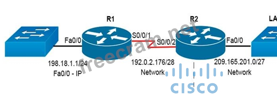
Central Florida Widgets recently installed a new router in their office. Complete the network installation by performing the initial router configurations and configuring R1PV2 routing using the router command line interface (CLI) on the RC.
Configure the router per the following requirements:
- Name of the router is R2
- Enable.secret password is cisco
- The password to access user EXEC mode using the console is cisco2
- The password to allow telnet access to the router is cisco3
IPV4 addresses mast be configured as follows:
- Ethernet network 209.165.201.0/27 - router has fourth assignable host address in subnet
- Serial network is 192.0.2.176/28 - router has last assignable host address in the subnet.
- Interfaces should be enabled.
- Router protocol is RIPV2
Attention:
In practical examinations, please note the following, the actual information will prevail.
1 . Name or the router is xxx
2 . EnablE. secret password is xxx
3 . Password In access user EXEC mode using the console is xxx
4 . The password to allow telnet access to the router is xxx
5 . IP information
Correct Answer:
See Explanation
Explanation/Reference:
Explanation:
Step 1:
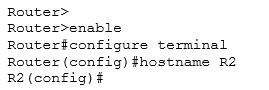
Click on the console host, you will get a pop-up screen CLI of Router.
Router>
Configure the new router as per the requirements provided in Lab question Requirement 1:
Name of the router is R2
Step 2:
To change the hostname of the router to R2 follow the below steps:
Requirement 2:
Enable-secret password is cisco1
Step 3:
To set the enable secret password to cisco1 use the following command
R2(config)#enable secret cisco1
Requirement 3:
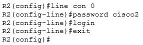
The password to access user EXEC mode using the console is cisco2
Step 4:
We need to configure the line console 0 with the password cisco2
Also remember to type login command after setting up the password on line con 0 which allows router to accept logins via console.
Requirement 4:
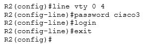
The password to allow telnet access to the router is cisco3
Step 5:
To allow telnet access we need to configure the vty lines 0 4 with the password cisco3 Also remember to type login command after setting up the password on line vty 0 4 which allows router to accept logins via telnet.
Requirement 5:
(5.1) Ethernet network 209.165.201.0 /27 - Router has the fourth assignable host address in subnet.
(5.2) Serial Network is 192.0.2.176 /28 - Router has the last assignable host address in subnet.
Step 6:
Ethernet network 209.165.201.0 /27 - Router has the fourth assignable host address in subnet.
Ethernet Interface on router R2 is Fast Ethernet 0/0 as per the exhibit First we need to identify the subnet mask Network: 209.165.201.0 /27 Subnet mask: /27: 27 bits = 8 + 8 + 8 + 3
=8(bits).8(bits).8(bits) .11100000 (3bits)
=255.255.255.11100000
=11100000 = 128+64+32+0+0+0+0+0
= 224
Subnet mask: 255.255.255.224
Different subnet networks and there valid first and last assignable host address range for above subnet mask are Subnet Networks :::::: Valid Host address range :::::: Broadcast address
209.165.201.0 :::::: 209.165.201.1 - 209.165.201.30 ::::: 209.165.201.31
209.165.201.32 :::::: 209.165.201.33 - 209.165.201.62 ::::: 209.165.201.63
209.165.201.64 :::::: 209.165.201.65 - 209.165.201.94 :::::: 209.165.201.95
209.165.201.96 :::::: 209.165.201.97 - 209.165.201.126 :::::: 209.165.201.127
209.165.201.128 :::::: 209.165.201.129 - 209.165.201.158 :::::: 209.165.201.159
209.165.201.160 :::::: 209.165.201.161 - 209.165.201.190 :::::: 209.165.201.191
209.165.201.192 :::::: 209.165.201.193 - 209.165.201.222 :::::: 209.165.201.223
209.165.201.224 :::::: 209.165.201.225 - 209.165.201.254 :::::: 209.165.201.255 Use above table information for network 209.165.201.0 /27 to identify First assignable host address: 209.165.201.1 Last assignable host address: 209.165.201.30
Fourth assignable host address: 209.165.201.4
This IP address (209.165.201.4) which we need to configure on Fast Ethernet 0/0 of the router using the subnet mask 255.255.255.224

Requirement 6:
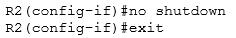
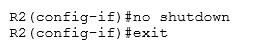
To enable interfaces
Use no shutdown command to enable interfaces
Step 7:
Serial Network is 192.0.2.176 /28 - Router has the last assignable host address in subnet.
Serial Interface on R2 is Serial 0/0/0 as per the exhibit
First we need to identify the subnet mask
Network: 192.0.2.176 /28
Subnet mask: /28: 28bits = 8bits+8bits+8bits+4bits
=8(bits).8(bits).8(bits) .11110000 (4bits)
=255.255.255.11100000
=11100000 = 128+64+32+16+0+0+0+0
= 240
Subnet mask: 255.255.255.240
Different subnet networks and there valid first and last assignable host address range for above subnet mask are Subnet Networks ::::: Valid Host address ::::::::::: Broadcast address
192.0.2.0 :::::: 192.0.2.1 - 192.0.2.14 ::::::: 192.0.2.15
192.0.2.16 ::::::: 192.0.2.17 - 192.0.2.30 ::::::: 192.0.2.31
192.0.2.32 :::::::: 192.0.2.33 - 192.0.2.46 :::::: 192.0.2.47
192.0.2.48 :::::: 192.0.2.49 - 192.0.2.62 ::::::: 192.0.2.64
192.0.2.64 ::::::: 192.0.2.65 - 192.0.2.78 ::::::: 192.0.2.79
192.0.2.80 :::::::: 192.0.2.81 - 192.0.2.94 :::::: 192.0.2.95
192.0.2.96 :::::: 192.0.2.97 - 192.0.2.110 ::::::: 192.0.2.111
192.0.2.112 ::::::: 192.0.2.113 - 192.0.2.126 ::::::: 192.0.2.127
192.0.2.128 :::::::: 192.0.2.129 - 192.0.2.142 :::::: 192.0.2.143
192.0.2.144 :::::: 192.0.2.145 - 192.0.2.158 ::::::: 192.0.2.159
192.0.2.160 ::::::: 192.0.2.161 - 192.0.2.174 ::::::: 192.0.2.175
192.0.2.176 :::::::: 192.0.2.177 - 192.0.2.190 :::::: 192.0.2.191
and so on ....
Use above table information for network 192.0.2.176 /28 to identify
First assignable host address: 192.0.2.177
Last assignable host address: 192.0.2.190
We need to configure Last assignable host address (192.0.2.190) on serial 0/0/0 using the subnet mask
255.255.255.240

Requirement 6:
To enable interfaces
Use no shutdown command to enable interfaces
Requirement 7:
Router protocol is RIPv2
Step 8:
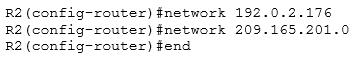
Need to enable RIPv2 on router and advertise its directly connected networks R2(config)#router rip To enable RIP v2 routing protocol on router use the command version 2 R2(config-router)#version 2
Optional: no auto-summary (Since LAB networks do not have discontinuous networks) RIP v2 is classless, and advertises routes including subnet masks, but it summarizes routes by default.
So the first things we need to do when configuring RIP v2 is turn off auto-summarization with the router command no auto-summary if you must perform routing between disconnected subnets.
R2 (config-router) # no auto-summary
Advertise the serial 0/0/0 and fast Ethernet 0/0 networks into RIP v2 using network command
Step 9:
Important please do not forget to save your running-config to startup-config R2# copy running-config startup-config
Explanation/Reference:
Explanation:
Step 1:
Click on the console host, you will get a pop-up screen CLI of Router.
Router>
Configure the new router as per the requirements provided in Lab question Requirement 1:
Name of the router is R2
Step 2:
To change the hostname of the router to R2 follow the below steps:
Requirement 2:
Enable-secret password is cisco1
Step 3:
To set the enable secret password to cisco1 use the following command
R2(config)#enable secret cisco1
Requirement 3:
The password to access user EXEC mode using the console is cisco2
Step 4:
We need to configure the line console 0 with the password cisco2
Also remember to type login command after setting up the password on line con 0 which allows router to accept logins via console.
Requirement 4:
The password to allow telnet access to the router is cisco3
Step 5:
To allow telnet access we need to configure the vty lines 0 4 with the password cisco3 Also remember to type login command after setting up the password on line vty 0 4 which allows router to accept logins via telnet.
Requirement 5:
(5.1) Ethernet network 209.165.201.0 /27 - Router has the fourth assignable host address in subnet.
(5.2) Serial Network is 192.0.2.176 /28 - Router has the last assignable host address in subnet.
Step 6:
Ethernet network 209.165.201.0 /27 - Router has the fourth assignable host address in subnet.
Ethernet Interface on router R2 is Fast Ethernet 0/0 as per the exhibit First we need to identify the subnet mask Network: 209.165.201.0 /27 Subnet mask: /27: 27 bits = 8 + 8 + 8 + 3
=8(bits).8(bits).8(bits) .11100000 (3bits)
=255.255.255.11100000
=11100000 = 128+64+32+0+0+0+0+0
= 224
Subnet mask: 255.255.255.224
Different subnet networks and there valid first and last assignable host address range for above subnet mask are Subnet Networks :::::: Valid Host address range :::::: Broadcast address
209.165.201.0 :::::: 209.165.201.1 - 209.165.201.30 ::::: 209.165.201.31
209.165.201.32 :::::: 209.165.201.33 - 209.165.201.62 ::::: 209.165.201.63
209.165.201.64 :::::: 209.165.201.65 - 209.165.201.94 :::::: 209.165.201.95
209.165.201.96 :::::: 209.165.201.97 - 209.165.201.126 :::::: 209.165.201.127
209.165.201.128 :::::: 209.165.201.129 - 209.165.201.158 :::::: 209.165.201.159
209.165.201.160 :::::: 209.165.201.161 - 209.165.201.190 :::::: 209.165.201.191
209.165.201.192 :::::: 209.165.201.193 - 209.165.201.222 :::::: 209.165.201.223
209.165.201.224 :::::: 209.165.201.225 - 209.165.201.254 :::::: 209.165.201.255 Use above table information for network 209.165.201.0 /27 to identify First assignable host address: 209.165.201.1 Last assignable host address: 209.165.201.30
Fourth assignable host address: 209.165.201.4
This IP address (209.165.201.4) which we need to configure on Fast Ethernet 0/0 of the router using the subnet mask 255.255.255.224
Requirement 6:
To enable interfaces
Use no shutdown command to enable interfaces
Step 7:
Serial Network is 192.0.2.176 /28 - Router has the last assignable host address in subnet.
Serial Interface on R2 is Serial 0/0/0 as per the exhibit
First we need to identify the subnet mask
Network: 192.0.2.176 /28
Subnet mask: /28: 28bits = 8bits+8bits+8bits+4bits
=8(bits).8(bits).8(bits) .11110000 (4bits)
=255.255.255.11100000
=11100000 = 128+64+32+16+0+0+0+0
= 240
Subnet mask: 255.255.255.240
Different subnet networks and there valid first and last assignable host address range for above subnet mask are Subnet Networks ::::: Valid Host address ::::::::::: Broadcast address
192.0.2.0 :::::: 192.0.2.1 - 192.0.2.14 ::::::: 192.0.2.15
192.0.2.16 ::::::: 192.0.2.17 - 192.0.2.30 ::::::: 192.0.2.31
192.0.2.32 :::::::: 192.0.2.33 - 192.0.2.46 :::::: 192.0.2.47
192.0.2.48 :::::: 192.0.2.49 - 192.0.2.62 ::::::: 192.0.2.64
192.0.2.64 ::::::: 192.0.2.65 - 192.0.2.78 ::::::: 192.0.2.79
192.0.2.80 :::::::: 192.0.2.81 - 192.0.2.94 :::::: 192.0.2.95
192.0.2.96 :::::: 192.0.2.97 - 192.0.2.110 ::::::: 192.0.2.111
192.0.2.112 ::::::: 192.0.2.113 - 192.0.2.126 ::::::: 192.0.2.127
192.0.2.128 :::::::: 192.0.2.129 - 192.0.2.142 :::::: 192.0.2.143
192.0.2.144 :::::: 192.0.2.145 - 192.0.2.158 ::::::: 192.0.2.159
192.0.2.160 ::::::: 192.0.2.161 - 192.0.2.174 ::::::: 192.0.2.175
192.0.2.176 :::::::: 192.0.2.177 - 192.0.2.190 :::::: 192.0.2.191
and so on ....
Use above table information for network 192.0.2.176 /28 to identify
First assignable host address: 192.0.2.177
Last assignable host address: 192.0.2.190
We need to configure Last assignable host address (192.0.2.190) on serial 0/0/0 using the subnet mask
255.255.255.240
Requirement 6:
To enable interfaces
Use no shutdown command to enable interfaces
Requirement 7:
Router protocol is RIPv2
Step 8:
Need to enable RIPv2 on router and advertise its directly connected networks R2(config)#router rip To enable RIP v2 routing protocol on router use the command version 2 R2(config-router)#version 2
Optional: no auto-summary (Since LAB networks do not have discontinuous networks) RIP v2 is classless, and advertises routes including subnet masks, but it summarizes routes by default.
So the first things we need to do when configuring RIP v2 is turn off auto-summarization with the router command no auto-summary if you must perform routing between disconnected subnets.
R2 (config-router) # no auto-summary
Advertise the serial 0/0/0 and fast Ethernet 0/0 networks into RIP v2 using network command
Step 9:
Important please do not forget to save your running-config to startup-config R2# copy running-config startup-config


- Question List (501q)
- Question 1: Which two statements about EIGRP on IPv6 networks are true? ...
- Question 2: Refer to the exhibit. A network technician is asked to desig...
- Question 3: SIMULATION Central Florida Widgets recently installed a new ...
- Question 4: A network administrator enters the following command on a ro...
- Question 5: Refer to the exhibit. What two results would occur if the hu...
- Question 6: Which feature allows a device to use a switch port that is c...
- Question 7: Configuration of which option is required on a Cisco switch ...
- Question 8: Which value must you configure on a device before EIGRP for ...
- Question 9: Which IEEE standard protocol is initiated as a result of suc...
- Question 10: Refer to the exhibit. Given the output shown from this Cisco...
- Question 11: Which command is used to display the collection of OSPF link...
- Question 12: Which two are features of IPv6? (Choose two.)...
- Question 13: (Exhibit) Refer to the exhibit. After you apply the given co...
- Question 14: SIMULATION CCNA.com has a small network that is using EIGRP ...
- Question 15: A network administrator is configuring ACLs on a Cisco route...
- Question 16: Which type of attack can be mitigated by configuring the def...
- Question 17: Refer to the exhibit. What statement is true of the configur...
- Question 18: Refer to the exhibit. Which statement is true? (Exhibit)...
- Question 19: In a switched environment, what does the IEEE 802.1Q standar...
- Question 20: Which three statements about Syslog utilization are true? (C...
- Question 21: Which component of the routing table ranks routing protocols...
- Question 22: OSPF enable on interface with multiple ipv6 prefix which ip ...
- Question 23: Which RPVST+ port state is excluded from all STP operations?...
- Question 24: Which networking Technology is currently recognized as the s...
- Question 25: While troubleshooting a connection problem on a computer, yo...
- Question 26: What are two characteristics of SSH? (Choose two.)...
- Question 27: Which two statements about the OSPF Router ID are true? (Cho...
- Question 28: Refer to the exhibit. A problem with network connectivity ha...
- Question 29: Which two statements about access points are true? (Choose t...
- Question 30: Which effect of the passive-interface command on R1 is true?...
- Question 31: What happens when an 802.11a node broadcasts within the rang...
- Question 32: What is the default administrative distance of OSPF?...
- Question 33: If you want multiple hosts on a network, where do you config...
- Question 34: Which statement about a router on a stick is true?...
- Question 35: Which three circumstances can cause a GRE tunnel to be in an...
- Question 36: Which of the following IP addresses fall into the CIDR block...
- Question 37: Scenario You are implementing EIGRP between the main office ...
- Question 38: Which NAT type is used to translate a single inside address ...
- Question 39: Why will a switch never learn a broadcast address?...
- Question 40: A router has two Fast Ethernet interfaces and needs to conne...
- Question 41: Refer to the exhibit. Which rule does the DHCP server use wh...
- Question 42: Which type of routing protocol operates by using first infor...
- Question 43: Which command can you enter in a network switch configuratio...
- Question 44: What is the default Syslog facility level?...
- Question 45: Which command can you enter to determine the addresses that ...
- Question 46: Refer to the exhibit. Router edge-1 is unable to establish O...
- Question 47: Which parameter would you tune to affect the selection of a ...
- Question 48: Which IPv6 address is valid?
- Question 49: Refer to the exhibit. An administrator pings the default gat...
- Question 50: Which MTU size can cause a baby giant error?...
- Question 51: Which type of routing protocol operates by exchanging the en...
- Question 52: SIMULATION A network associate is adding security to the con...
- Question 53: Refer to the exhibit. (Exhibit) Based on the exhibited routi...
- Question 54: Which major component of the Cisco network virtualization ar...
- Question 55: Refer to the graphic. It has been decided that Workstation 1...
- Question 56: Refer to the exhibit. The network administrator normally est...
- Question 57: Which statements describe the routing protocol OSPF? (Choose...
- Question 58: Which command displays CPU utilization?...
- Question 59: When enabled, which feature prevents routing protocols from ...
- Question 60: Refer to the exhibit. A network administrator configures a n...
- Question 61: Under which circumstance should a network administrator impl...
- Question 62: Refer to the exhibit. C-router is to be used as a "router-on...
- Question 63: Refer to the exhibit. Which statement describes the effect o...
- Question 64: Refer to the exhibit. Which subnet mask will place all hosts...
- Question 65: The following configuration line was added to router R1 Acce...
- Question 66: (Exhibit) Refer to the exhibit. A new subnet with 60 hosts h...
- Question 67: How should a router that is being used in a Frame Relay netw...
- Question 68: Which option describes the purpose of traffic policing?...
- Question 69: Which command you enter on a switch to display the ip addres...
- Question 70: Refer to the exhibit. Which command do you enter so that R1 ...
- Question 71: Refer to the exhibit. An attempt to deny web access to a sub...
- Question 72: What command is used to verify the DLCI destination address ...
- Question 73: What command instructs the device to timestamp Syslog debug ...
- Question 74: Which two statements about static NAT translations are true?...
- Question 75: Which value is used to determine the active router in an HSR...
- Question 76: Which three encapsulation layers in the OSI model are combin...
- Question 77: While troubleshooting a DCHP client that is behaving erratic...
- Question 78: Refer to the exhibit. What can be determined about the route...
- Question 79: What is the purpose of Inverse ARP?...
- Question 80: Which command encrypts all plaintext passwords?...
- Question 81: It has become necessary to configure an existing serial inte...
- Question 82: Refer to the exhibit. What commands must be configured on th...
- Question 83: Which port security violation mode allows traffic from valid...
- Question 84: You enter the show ipv6 route command on an OSPF device and ...
- Question 85: Refer to the exhibit. Which address range efficiently summar...
- Question 86: Which option is the main function of congestion management?...
- Question 87: In which CLI configuration mode can you configure the hostna...
- Question 88: The Frame Relay network in the diagram is not functioning pr...
- Question 89: What are two characteristics of Frame Relay point-to-point s...
- Question 90: A network administrator has configured access list 173 to pr...
- Question 91: Which statement about named ACLs is true?...
- Question 92: Refer to exhibit: Which destination addresses will be used b...
- Question 93: Refer to the exhibit A frame on vlan 1on switch s1 is sent t...
- Question 94: In which circumstance are multiple copies of the same unicas...
- Question 95: DRAG DROP Routing has been configured on the local touter wi...
- Question 96: What is a global command?
- Question 97: (Exhibit) Refer to the exhibit. All switch ports are assigne...
- Question 98: Refer to the exhibit. The technician wants to upload a new I...
- Question 99: Which two protocols are used by bridges and/or switches to p...
- Question 100: Refer to the exhibit. When running EIGRP, what is required f...
- Question 101: DRAG DROP Drag and drop the DNS lookup commands from the lef...
- Question 102: A national retail chain needs to design an IP addressing sch...
- Question 103: Which of the following statements describe the network shown...
- Question 104: Assuming a subnet mask of 255.255.248.0, three of the follow...
- Question 105: Which command can you use to manually assign a static IPv6 a...
- Question 106: Which one of these is a valid HSRP Virtual Mac Address?...
- Question 107: Which command would you use on a Cisco router to verify the ...
- Question 108: Refer to the exhibit. For what two reasons has the router lo...
- Question 109: Which action can change the order of entries in a named acce...
- Question 110: Instructions This item containes several questions that you ...
- Question 111: SIMULATION A network associate is adding security to the con...
- Question 112: On which type of device is every port in the same collision ...
- Question 113: Which command can you enter on a switch to determine the cur...
- Question 114: Which RFC was created to alleviate the depletion of IPv4 pub...
- Question 115: Which route source code represents the routing protocol with...
- Question 116: (Exhibit) Refer to the exhibit. On R1, which routing protoco...
- Question 117: RouterA is unable to reach RouterB. Both routers are running...
- Question 118: Which three are the components of SNMP? (Choose three)...
- Question 119: What is the effect of the overload keyword in a static NAT t...
- Question 120: Refer to Exhibit. How many broadcast domains are shown in th...
- Question 121: In a GLBP network, who is responsible for the arp request?...
- Question 122: Which statement about static routes is true?...
- Question 123: Refer to the exhibit. How many broadcast domains exist in th...
- Question 124: Scenario (Exhibit) An administrator is trying to ping and te...
- Question 125: Instructions This item containes several questions that you ...
- Question 126: Refer to the exhibit. What is the reason that the interface ...
- Question 127: What is a possible reason why a host is able to ping a web s...
- Question 128: Refer to the exhibit. In this VLSM addressing scheme, what s...
- Question 129: Which protocol is an open standard protocol framework that i...
- Question 130: DRAG DROP Drag the Cisco default administrative distance to ...
- Question 131: Which component of a routing table entry represents the subn...
- Question 132: What is the alternative notation for the IPv6 address B514:8...
- Question 133: Refer to the exhibit. Switch port FastEthernet 0/24 on ALSwi...
- Question 134: (Exhibit) Refer to the exhibit. Assuming that the entire net...
- Question 135: What is the first step you perform to configure an SNMPv3 us...
- Question 136: Refer to the exhibit. The speed of all serial links is E1 an...
- Question 137: Given an IP address 172.16.28.252 with a subnet mask of 255....
- Question 138: In order to comply with new auditing standards, a security a...
- Question 139: What levels will be trapped if the administrator executes th...
- Question 140: Which command can you enter to configure a local username wi...
- Question 141: Refer to the topology below and answer the following questio...
- Question 142: Refer to the exhibit. A network administrator attempts to pi...
- Question 143: What are the benefit of using Netflow? (Choose three.)...
- Question 144: Refer to the exhibit. Which WAN protocol is being used? (Exh...
- Question 145: Which three options are the HSRP states for a router? (Choos...
- Question 146: Refer to the exhibit. The network administrator is in a camp...
- Question 147: Refer to the exhibit. A frame on VLAN 1 on switch S1 is sent...
- Question 148: Which option is the default switch port port-security violat...
- Question 149: Which subnet mask would be appropriate for a network address...
- Question 150: Cisco Catalyst switches CAT1 and CAT2 have a connection betw...
- Question 151: Assuming the default switch configuration which vlan range c...
- Question 152: Which destination IP address can a host use to send one mess...
- Question 153: Refer to the exhibit. Which two statements are true of the i...
- Question 154: Which configuration can be used with PAT to allow multiple i...
- Question 155: Which statement about switch access ports is true?...
- Question 156: What SNMP message alerts the manager to a condition on the n...
- Question 157: Refer to the topology below and answer the following questio...
- Question 158: Scenario You are implementing EIGRP between the main office ...
- Question 159: Which two statements about switch stacking are true? (Choose...
- Question 160: Which of the following describes the roles of devices in a W...
- Question 161: Refer to exhibit. A network administrator cannot establish a...
- Question 162: Which three are characteristics of an IPv6 anycast address? ...
- Question 163: What are three factors a network administrator must consider...
- Question 164: Refer to the exhibit. The two connected ports on the switch ...
- Question 165: Which statement about the inside interface configuration in ...
- Question 166: Refer to the exhibit. What is the meaning of the term dynami...
- Question 167: Refer to the topology. Your company has decided to connect t...
- Question 168: Which statement about upgrading a cisco IOS device with TFTP...
- Question 169: (Exhibit) What destination Layer 2 address will be used in t...
- Question 170: Instructions This item containes several questions that you ...
- Question 171: Refer to the exhibit. According to the routing table, where ...
- Question 172: An administrator is unsuccessful in adding VLAN 50 to a swit...
- Question 173: When you deploy multilink PPP on your network, where must yo...
- Question 174: Which of the following are types of flow control? (Choose th...
- Question 175: Which value must a device send as its username when using CH...
- Question 176: Refer to the exhibit. The network administrator must establi...
- Question 177: Which command reveals the last method used to powercycle a r...
- Question 178: Refer to the exhibit. What is the effect of the configuratio...
- Question 179: Which two commands can be used to verify a trunk link config...
- Question 180: Before installing a new, upgraded version of the IOS, what s...
- Question 181: DRAG DROP Drag each definition on the left to the matching t...
- Question 182: What information does a router running a link-state protocol...
- Question 183: Which type does a port become when it receives the best BPDU...
- Question 184: What Netflow component can be applied to an interface to tra...
- Question 185: Which command must you enter to enable OSPFV2 in an IPV4 net...
- Question 186: Refer to the diagram. All hosts have connectivity with one a...
- Question 187: What can be done to secure the virtual terminal interfaces o...
- Question 188: How can you disable DTP on a switch port?...
- Question 189: Which two statements about extended traceroute command are t...
- Question 190: Refer to the exhibit. A technician is troubleshooting host c...
- Question 191: In GLBP, which router will respond to client ARP requests?...
- Question 192: What is the result of issuing the frame-relay map ip 192.168...
- Question 193: What are three advantages of vlans?...
- Question 194: Which option is the industry-standard protocol for EtherChan...
- Question 195: This graphic shows the results of an attempt to open a Telne...
- Question 196: Which two command can you enter to display the current time ...
- Question 197: What is one benefit of PVST+?
- Question 198: Refer to the exhibit. Given this output for SwitchC, what sh...
- Question 199: Which symptom most commonly indicates that two connecting in...
- Question 200: Refer to the exhibit. What will Router1 do when it receives ...
- Question 201: Which two options are the best reasons to use an IPv4 privat...
- Question 202: Which statement about access lists that are applied to an in...
- Question 203: Refer to the exhibit. Based on the information given, which ...
- Question 204: When you are troubleshooting an ACL issue on a router, which...
- Question 205: How does using the service password-encryption command on a ...
- Question 206: SIMULATION The following have already been configured on the...
- Question 207: Refer to the exhibit. In the Frame Relay network, which IP a...
- Question 208: Refer to the exhibit. What is the meaning of the output MTU ...
- Question 209: Refer to the exhibit. Given the output for this command, if ...
- Question 210: Which additional configuration step is necessary in order to...
- Question 211: Which two options are fields in an Ethernet frame? (Choose t...
- Question 212: Which two statements about TACACS+ are true? (Choose two.)...
- Question 213: Which of the following correctly describe steps in the OSI d...
- Question 214: Refer to the exhibit: (Exhibit) After you apply the give con...
- Question 215: Refer to the exhibit. What is the most efficient summarizati...
- Question 216: Refer to the exhibit. After a RIP route is marked invalid on...
- Question 217: What is one reason that WPA encryption is preferred over WEP...
- Question 218: DRAG DROP Drag and drop the protocols from the left onto the...
- Question 219: Refer to the graphic. A static route to the 10.5.6.0/24 netw...
- Question 220: Refer to the exhibit. The network shown in the diagram is ex...
- Question 221: Which option is the main function of congestion management?...
- Question 222: A network administrator is verifying the configuration of a ...
- Question 223: Which two statements about VTP are true? (Choose two.)...
- Question 224: Which process is associated with spanning-tree convergence?...
- Question 225: Which option is the benefit of implementing an intelligent D...
- Question 226: What will be the result if the following configuration comma...
- Question 227: Which three statements about the features of SNMPv2 and SNMP...
- Question 228: What Cisco IOS feature can be enabled to pinpoint an applica...
- Question 229: Which three options are the major components of a network vi...
- Question 230: Refer to the exhibit. HostA cannot ping HostB. Assuming rout...
- Question 231: Which type of EIGRP route entry describes a feasible success...
- Question 232: Where does routing occur within the DoD TCP/IP reference mod...
- Question 233: What occurs on a Frame Relay network when the CIR is exceede...
- Question 234: Refer to the exhibit. Why has this switch not been elected t...
- Question 235: What are the requirement to configure DHCP binding? (Choose ...
- Question 236: What are the Popular destinations for syslog messages to be ...
- Question 237: What are three values that must be the same within a sequenc...
- Question 238: Which three of these statements regarding 802.1Q trunking ar...
- Question 239: (Exhibit) Which connection uses the default encapsulation fo...
- Question 240: DRAG DROP Drag and drop the STP features from the left onto ...
- Question 241: Which two options are valid WAN connectivity methods? (Choos...
- Question 242: Refer to the exhibit. How should the FastEthernet0/1 ports o...
- Question 243: When a DHCP server is configured, which two IP addresses sho...
- Question 244: Refer to the exhibit. Which three statements correctly descr...
- Question 245: Which technology supports the stateless assignment of IPv6 a...
- Question 246: Refer to the topology below and answer the following questio...
- Question 247: How does a DHCP server dynamically assign IP addresses to ho...
- Question 248: Which statement about MPLS is true?...
- Question 249: When is a routing table entry identified as directly connect...
- Question 250: Which statement about LLDP is true?...
- Question 251: Which two IP SLA operations can you use to measure the end-t...
- Question 252: Which parameter or parameters are used to calculate OSPF cos...
- Question 253: Which device allows users to connect to the network using a ...
- Question 254: On which options are standard access lists based?...
- Question 255: The network administrator is asked to configure 113 point-to...
- Question 256: Refer to the topology shown in the exhibit. Which ports will...
- Question 257: Which address block identifies all link-local addresses?...
- Question 258: At which layer of the OSI model does PPP perform?...
- Question 259: Scenario (Exhibit) An administrator is trying to ping and te...
- Question 260: Which command do use we to see SNMP version...
- Question 261: A network interface port has collision detection and carrier...
- Question 262: Which option describes a difference between EIGRP for IPv4 a...
- Question 263: Which command shows your active Telnet connections?...
- Question 264: Refer to the exhibit. A network administrator is configuring...
- Question 265: An administrator must assign static IP addresses to the serv...
- Question 266: Refer to exhibit. What Administrative distance has route to ...
- Question 267: SIMULATION A network associate is adding security to the con...
- Question 268: (Exhibit) Refer to the exhibit. Which user-mode password has...
- Question 269: After you configure the ip dns spoofing command globally on ...
- Question 270: Which two steps must you perform on each device that is conf...
- Question 271: Which major IPv6 address type is supported in IPv4 but rarel...
- Question 272: Which protocol does ipv6 use to discover other ipv6 nodes on...
- Question 273: What two things will a router do when running a distance vec...
- Question 274: Scenario You are implementing EIGRP between the main office ...
- Question 275: What is the alert message generated by SNMP agents called?...
- Question 276: DRAG DROP Order the DHCP message types as they would occur b...
- Question 277: All WAN links inside the ABC University network use PPP with...
- Question 278: Which feature can you use to restrict SNMP queries to a spec...
- Question 279: Which two are advantages of static routing when compared to ...
- Question 280: Which address class includes network 191.168.0.1/27?...
- Question 281: Refer to the exhibit. Refer to the exhibit. After HostA ping...
- Question 282: Host 1 is trying to communicate with Host 2. The e0 interfac...
- Question 283: Which type of topology is required by DMVPN?...
- Question 284: If IP routing is enabled, which two commands set the gateway...
- Question 285: Which two components are used to identify a neighbor in a BG...
- Question 286: Refer to the exhibit. Statements A, B, C, and D of ACL 10 ha...
- Question 287: Which routing protocol has the smallest default administrati...
- Question 288: On a corporate network, hosts on the same VLAN can communica...
- Question 289: Refer to the exhibit. A network administrator is adding two ...
- Question 290: Which NTP command configures the local devices as an NTP ref...
- Question 291: What is the function of the command switchport trunk native ...
- Question 292: Users on the 172.17.22.0 network cannot reach the server loc...
- Question 293: Which two passwords must be supplied in order to connect by ...
- Question 294: Refer to the exhibit. The two exhibited devices are the only...
- Question 295: Which functionality does an SVI provide?...
- Question 296: The output of the show frame-relay pvc command shows "PVC ST...
- Question 297: On a network of one department, there are four PCs connected...
- Question 298: (Exhibit) A static map to the S-AMER location is required. W...
- Question 299: Which dynamic routing protocol uses only the hop count to de...
- Question 300: Refer to the exhibit. (Exhibit) A network associate has conf...
- Question 301: VLAN 3 is not yet configured on your switch. What happens if...
- Question 302: What are three features of the IPV6 protocol? (Choose three....
- Question 303: What are three benefits of GLBP? (Choose three.)...
- Question 304: Which value is indicated by the next hop in a routing table?...
- Question 305: Which encapsulation type is a Frame Relay encapsulation type...
- Question 306: What command sequence will configure a router to run OSPF an...
- Question 307: A network administrator creates a layer 3 EtherChannel, bund...
- Question 308: When is the most appropriate time to escalate an issue that ...
- Question 309: Refer to the exhibit. Which statement describes DLCI 17? (Ex...
- Question 310: DRAG DROP Drag the frame relay acronym on the left to match ...
- Question 311: When a device learns multiple routes to a specific network, ...
- Question 312: DRAG DROP Drag and drop the DHCP client states from the left...
- Question 313: Instructions This item containes several questions that you ...
- Question 314: How is provided master redundancy on a stacked switches?...
- Question 315: Which statement describes VRRP object tracking?...
- Question 316: What are two benefits of using a single OSPF area network de...
- Question 317: Which option is a valid IPv6 address?...
- Question 318: Refer to the exhibit. The output that is shown is generated ...
- Question 319: Refer to the exhibit. What set of commands was configured on...
- Question 320: What is the effect of using the service password-encryption ...
- Question 321: At which layer of the OSI model is RSTP used to prevent loop...
- Question 322: Which option is a benefit of switch stacking?...
- Question 323: When you troubleshoot an IPv4 connectivity issue on a router...
- Question 324: The command frame-relay map ip 10.121.16.8 102 broadcast was...
- Question 325: What does a Layer 2 switch use to decide where to forward a ...
- Question 326: What authentication type is used by SNMPv2?...
- Question 327: While troubleshooting a GRE tunnel interface issue, show int...
- Question 328: Which value can you modify to configure a specific interface...
- Question 329: What is the most efficient subnet mask for a point to point ...
- Question 330: Which statement about VLAN configuration is true?...
- Question 331: Which technology supports multiple dynamic secure connection...
- Question 332: Which function enables an administrator to route multiple VL...
- Question 333: Which two statements about RIPv2 are true? (Choose two.)...
- Question 334: Which port state is introduced by Rapid-PVST?...
- Question 335: Based on the network shown in the graphic. Which option cont...
- Question 336: What are three reasons to collect Netflow data on a company ...
- Question 337: Scenario (Exhibit) An administrator is trying to ping and te...
- Question 338: Which PPP subprotocol negotiates authentication options?...
- Question 339: What are two statement for SSH?...
- Question 340: Which IPv6 address is the equivalent of the IPv4 interface l...
- Question 341: What are three approaches that are used when migrating from ...
- Question 342: Which IPv6 routing protocol uses multicast group FF02::9 to ...
- Question 343: Refer to the exhibit. A network associate has configured the...
- Question 344: Which statement describes the process of dynamically assigni...
- Question 345: Which 3 feature are represented by A letter in AAA? (Choose ...
- Question 346: Which technology can enable multiple VLANs to communicate wi...
- Question 347: A default Frame Relay WAN is classified as what type of phys...
- Question 348: SIMULATION A corporation wants to add security to its networ...
- Question 349: As a CCNA candidate, you must have a firm understanding of t...
- Question 350: Which two statements about eBGP neighbor relationships are t...
- Question 351: When a router makes a routing decision for a packet that is ...
- Question 352: You are working in a data center environment and are assigne...
- Question 353: What OSPF command, when configured, will include all interfa...
- Question 354: Which entity assigns IPv6 addresses to end users?...
- Question 355: In which two situations should you use out-of-band managemen...
- Question 356: Refer to the graphic. Host A is communicating with the serve...
- Question 357: Which NTP type designates a router without an external refer...
- Question 358: Which tunneling mechanism embeds an IPv4 address within an I...
- Question 359: SIMULATION A network associate is configuring a router for t...
- Question 360: Which Type of ipv6 unicast ip address is reachable across th...
- Question 361: Which method does a connected trunk port use to tag VLAN tra...
- Question 362: Which three statements about IPv6 address fd14:920b:f83d:407...
- Question 363: Which two statements about IPv6 address 2002:ab10:beef::/48 ...
- Question 364: A network administrator needs to allow only one Telnet conne...
- Question 365: Which statement about native VLAN traffic is true?...
- Question 366: When troubleshooting Ethernet connectivity issues, how can y...
- Question 367: A receiving host computes the checksum on a frame and determ...
- Question 368: A network administrator is trying to add a new router into a...
- Question 369: Which value must the device send as its username when using ...
- Question 370: What is one requirement for interfaces to run IPv6?...
- Question 371: Refer to the exhibit. (Exhibit) You determine that Computer ...
- Question 372: What can you change to select switch as root bridge?...
- Question 373: Refer to the topology below and answer the following questio...
- Question 374: Refer to the exhibit. Which address and mask combination rep...
- Question 375: Which parameter or parameters are used to calculate OSPF cos...
- Question 376: Which protocol is a Cisco proprietary implementation of STP?...
- Question 377: While troubleshooting a connectivity issue from a PC you obt...
- Question 378: DRAG DROP Drag and drop the IEEE standard cable names from t...
- Question 379: Refer to the graphic. R1 is unable to establish an OSPF neig...
- Question 380: Which two statistics appear in show frame-relay map output? ...
- Question 381: Which IPv6 address is the all-router multicast group?...
- Question 382: DRAG DROP Drag and drop the QoS features from the left onto ...
- Question 383: Which definition of default route is true?...
- Question 384: Which two statements describe the process identifier that is...
- Question 385: For which two reasons might be you choose chassis aggregatio...
- Question 386: DRAG DROP Drag the security features on the left to the spec...
- Question 387: Three switches are connected to one another via trunk ports....
- Question 388: What is the default maximum number of equal-cost paths that ...
- Question 389: Refer to the exhibit. The network is converged. After link-s...
- Question 390: What does it take for BGP to establish connection? (Choose t...
- Question 391: Which protocol can cause overload on a CPU of a managed devi...
- Question 392: Refer to the exhibit. If the router Cisco returns the given ...
- Question 393: Which two types of information are held in the mac address t...
- Question 394: For which two protocols can PortFast alleviate potential hos...
- Question 395: Which item represents the standard IP ACL?...
- Question 396: DRAG DROP Match the terms on the left with the appropriate O...
- Question 397: When a router undergoes the exchange protocol within OSPF, i...
- Question 398: Which two types of information are held in the MAC address t...
- Question 399: What is the default lease time for a DHCP binding?...
- Question 400: Refer to the exhibit. Given the output from the show ip eigr...
- Question 401: Users have been complaining that their Frame Relay connectio...
- Question 402: Which command can be used from a PC to verify the connectivi...
- Question 403: Refer to the exhibit. When running OSPF, what would cause ro...
- Question 404: Which statement about the IP SLAs ICMP Echo operation is tru...
- Question 405: Which Cisco Catalyst feature automatically disables the port...
- Question 406: The network administrator has been asked to give reasons for...
- Question 407: Which feature must you enable to distribute vlans automatica...
- Question 408: The access control list shown in the graphic has been applie...
- Question 409: Scenario You are implementing EIGRP between the main office ...
- Question 410: Which two benefits are provided by creating VLANs? (Choose t...
- Question 411: A switch is configured with all ports assigned to vlan 2 wit...
- Question 412: Which NTP command configures the local device as an NTP refe...
- Question 413: Which term describes a spanning-tree network that has all sw...
- Question 414: Refer to the exhibit. Hosts in network 192.168.2.0 are unabl...
- Question 415: Refer to the exhibit. The network administrator requires eas...
- Question 416: Which of the following are key characteristics of PPP? (Choo...
- Question 417: Which statement describes the process ID that is used to run...
- Question 418: Which two benefits are provided by using a hierarchical addr...
- Question 419: In which two circumstances are private IPv4 addresses approp...
- Question 420: Which command allows you to verify the encapsulation type (C...
- Question 421: Which of these represents an IPv6 link-local address?...
- Question 422: What is a difference between TACACS+ and RADIUS in AAA?...
- Question 423: DRAG DROP An interface has been configured with the access l...
- Question 424: Which two switch states are valid for 802.1w? (Choose two.)...
- Question 425: Based on the output below from SwitchB, which statement is t...
- Question 426: An access list was written with the four statements shown in...
- Question 427: Which statement about IPv6 link-local addresses is true?...
- Question 428: Why do large OSPF networks use a hierarchical design? (Choos...
- Question 429: Refer to the exhibit. Host A pings interface S0/0 on router ...
- Question 430: Which statement about unicast frame forwarding on a switch i...
- Question 431: Which command is used to enable CHAP authentication, with PA...
- Question 432: What are the three things that the Netflow uses to consider ...
- Question 433: What are three components that comprise the SNMP framework? ...
- Question 434: Which three elements must be used when you configure a route...
- Question 435: DRAG DROP Drag and drop the BGP components from the left ont...
- Question 436: What is the function of the command switchport trunk native ...
- Question 437: Which are valid modes for a switch port used as a VLAN trunk...
- Question 438: Refer to the exhibit. The access list has been configured on...
- Question 439: Refer to the exhibit. How should the FastEthernet0/1 port on...
- Question 440: DRAG DROP Drag and drop the extended traceroute options from...
- Question 441: A router receives information about network 192.168.10.0/24 ...
- Question 442: Which three are valid modes for a switch port used as a VLAN...
- Question 443: Which command can you enter to determine whether serial inte...
- Question 444: Refer to the exhibit. The network administrator has created ...
- Question 445: How many bits are contained in each field of an IPv6 address...
- Question 446: Where information about untrusted hosts are stored?...
- Question 447: The following access list below was applied outbound on the ...
- Question 448: Which switch would STP choose to become the root bridge in t...
- Question 449: Which commands are required to properly configure a router t...
- Question 450: Which command can you enter to troubleshoot the failure of a...
- Question 451: Which three features are added in SNMPv3 over SNMPv2?...
- Question 452: What is a valid HSRP virtual MAC address?...
- Question 453: Instructions This item containes several questions that you ...
- Question 454: For which two reasons was RFC 1918 address space defining (C...
- Question 455: Which type of secure MAC address must be configured manually...
- Question 456: What value is primarily used to determine which port becomes...
- Question 457: Which two tasks does the Dynamic Host Configuration Protocol...
- Question 458: Which command can you enter to create a NAT pool of 6 addres...
- Question 459: Refer to the exhibit. The Lakeside Company has the internetw...
- Question 460: Which technology allows a large number of private IP address...
- Question 461: Refer to the exhibit. Which two statements are true about in...
- Question 462: As a network administrator, you have been instructed to prev...
- Question 463: Which two statements describe characteristics of IPv6 unicas...
- Question 464: Syslog was configured with a level 3 trap. Which 4 types of ...
- Question 465: Which type of secure MAC address must be configured manually...
- Question 466: Which three commands are required to enable NTP authenticati...
- Question 467: DRAG DROP A user is unable to connect to the Internet. Based...
- Question 468: Which three statements about DWDM are true? (Choose three)...
- Question 469: Refer to the exhibit. The company uses EIGRP as the routing ...
- Question 470: Which two authentic methods are compatible with MLPPP on a s...
- Question 471: Which IPV6 function serves the same purpose as ARP entry ver...
- Question 472: Which task must you perform to enable an IOS device to use D...
- Question 473: (Exhibit) Refer to the exhibit. If the devices produced the ...
- Question 474: Which header field is new on IPv6?...
- Question 475: Which IPsec security protocol should be used when confidenti...
- Question 476: Which of the port is not part of STP protocol?...
- Question 477: VLAN 3 is not yet configured on your switch. What happens if...
- Question 478: Which two link protocols are used to carry multiple VLANs ov...
- Question 479: Refer to the exhibit. What is the cause of the Syslog output...
- Question 480: By default, how many MAC addresses are permitted to be learn...
- Question 481: How is an EUI-64 format interface ID created from a 48-bit M...
- Question 482: Under which circumstance is a router on a stick most appropr...
- Question 483: Which command enables RSTP on a switch?...
- Question 484: Which statement about recovering a password on a Cisco route...
- Question 485: Which network topology allows all traffic to flow through a ...
- Question 486: Which two locations can be configured as a source for the IO...
- Question 487: What is the danger of the permit any entry in a NAT access l...
- Question 488: Which three statements about HSRP operation are true? (Choos...
- Question 489: Assuming the default switch configuration, which VLAN range ...
- Question 490: Which address prefix does OSPFv3 use when multiple IPv6 addr...
- Question 491: Which router IOS commands can be used to troubleshoot LAN co...
- Question 492: DRAG DROP Drag and drop the values in a routing table from t...
- Question 493: Which statement about routing protocols is true?...
- Question 494: Which type of broadcast barely used in IPv4 which also exist...
- Question 495: (Exhibit) If required, what password should be on the router...
- Question 496: A network administrator wants to add a line to an access lis...
- Question 497: If two OSPF neighbors have formed complete adjacency and are...
- Question 498: Refer to the exhibit. What set of commands was configured on...
- Question 499: Which two types of NAT addresses are used in a Cisco NAT dev...
- Question 500: What command visualizes the general NetFlow data on the comm...
- Question 501: Which two statements about stacking Cisco switches are true?...
