<< Prev Question Next Question >>
Question 76/81
SIMULATION
Scenario
You work as Network Engineer for RADO Network Ltd company. Your colleague has set up a РОС lab that simulates a customer network to study about the behavior of BGP protocol when routes are exchanged between two different autonomous systems.
Review the topology. You must identify and fix IBGP and EBGP issues on R1 router.
Topology Details
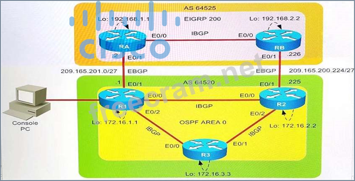
AS64520
R1, R2, and R3 are three routers on AS 64520, and OSPF is the IGP routing protocol that is configured

between them.
IBGP is configured between R1, R2, and R3 routers using peer group.
Loopback0 address is used for IBGP peering. Loopback0 address configured on R1, R2, and R3 are
advertised into BGP domain on AS64525.
AS64525
RA and RB are two routers on AS 64525, and EIGRP is the IGP routing protocol that is configured
between them.
Loopback0 address is used for IBGP peering. Loopback0 address is configured on RA and RB and it is
advertised into the BGP domain on AS64525.
R1 and RA form a EBGP neighbor relationship using a physical interface address.
R2 and RB form a EBGP neighbor relationship using a physical interface address.
Simulation Requirements
Identify and fix the EBGP neighbor relationship issue between R1 and RA routers.
Identify and fix the IBGP neighbor relationship issue between R1 and R2, and R1, and R3.
You are allowed to remove any misconfiguration or incorrect configuration to only fix the issue. Other
initial configurations that do not impact the issues must not be changed.
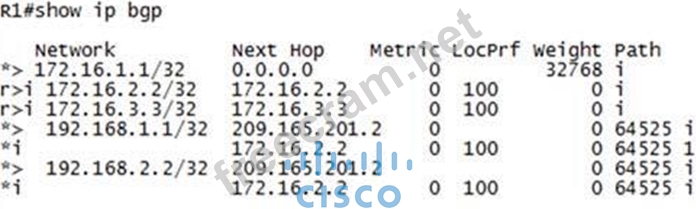
After you fix two issues on the R1 router, the final BGP table must appear as shown here.
Special Note: To gain the maximum number of points, you must fix IBGP and EBGP neighbor issues on router R1.
BGP must be configured without using address families. Do not change the BGP peer group
name.
Console logging and debugging features are disabled.
Use show commands to verify the BGP neighbor relationship.
Instructions
To configure a router, click the console host icon in the topology.
To view the different windows, click the buttons at the bottom of the window.
To minimize the windows, click the [-]. To move a window, drag it by the title bar.
Most commands that use the "Control" or "Escape" keys are not supported and are not necessary to complete this simulation. The help command does not display all commands of the help system.
Console access is available to router R1.
The password that is configured on router R1 is cisco (all small letters).
(Console cable is connected between PC and R1.)
Topology
Scenario
You work as Network Engineer for RADO Network Ltd company. Your colleague has set up a РОС lab that simulates a customer network to study about the behavior of BGP protocol when routes are exchanged between two different autonomous systems.
Review the topology. You must identify and fix IBGP and EBGP issues on R1 router.
Topology Details
AS64520
R1, R2, and R3 are three routers on AS 64520, and OSPF is the IGP routing protocol that is configured
between them.
IBGP is configured between R1, R2, and R3 routers using peer group.
Loopback0 address is used for IBGP peering. Loopback0 address configured on R1, R2, and R3 are
advertised into BGP domain on AS64525.
AS64525
RA and RB are two routers on AS 64525, and EIGRP is the IGP routing protocol that is configured
between them.
Loopback0 address is used for IBGP peering. Loopback0 address is configured on RA and RB and it is
advertised into the BGP domain on AS64525.
R1 and RA form a EBGP neighbor relationship using a physical interface address.
R2 and RB form a EBGP neighbor relationship using a physical interface address.
Simulation Requirements
Identify and fix the EBGP neighbor relationship issue between R1 and RA routers.
Identify and fix the IBGP neighbor relationship issue between R1 and R2, and R1, and R3.
You are allowed to remove any misconfiguration or incorrect configuration to only fix the issue. Other
initial configurations that do not impact the issues must not be changed.
After you fix two issues on the R1 router, the final BGP table must appear as shown here.
Special Note: To gain the maximum number of points, you must fix IBGP and EBGP neighbor issues on router R1.
BGP must be configured without using address families. Do not change the BGP peer group
name.
Console logging and debugging features are disabled.
Use show commands to verify the BGP neighbor relationship.
Instructions
To configure a router, click the console host icon in the topology.
To view the different windows, click the buttons at the bottom of the window.
To minimize the windows, click the [-]. To move a window, drag it by the title bar.
Most commands that use the "Control" or "Escape" keys are not supported and are not necessary to complete this simulation. The help command does not display all commands of the help system.
Console access is available to router R1.
The password that is configured on router R1 is cisco (all small letters).
(Console cable is connected between PC and R1.)
Topology