Valid 200-310 Dumps shared by ExamDiscuss.com for Helping Passing 200-310 Exam! ExamDiscuss.com now offer the newest 200-310 exam dumps, the ExamDiscuss.com 200-310 exam questions have been updated and answers have been corrected get the newest ExamDiscuss.com 200-310 dumps with Test Engine here:
Access 200-310 Dumps Premium Version
(392 Q&As Dumps, 35%OFF Special Discount Code: freecram)
<< Prev Question Next Question >>
Question 103/158
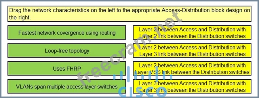
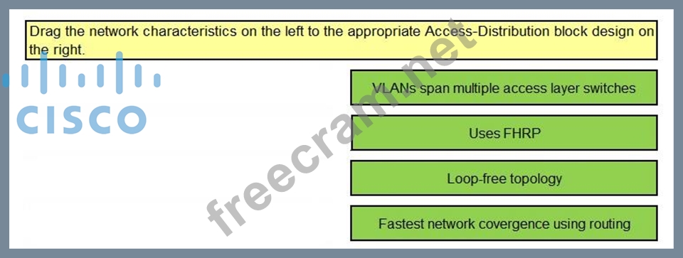
Select and Place:
Correct Answer:
Explanation/Reference:
I changed this answer to reflect CCDP explanation:
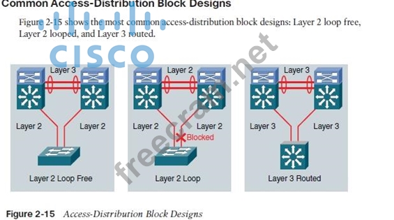
■ Layer 2 loop-free design: In this design, the access switches use Layer 2 switching. The links between the access and distribution layers are configured as Layer 2 trunks. The link between the distribution switches is configured as a Layer 3 routed link. An EtherChannel is typically used for this link to increase availability. In this design, there are no Layer 2 loops in the access-distribution block, which means that the Spanning Tree Protocol is not involved in network convergence and load balancing. All the ports are in the spanning-tree Forwarding state. Load balancing of the traffic from the access to the distribution layer is based on the First Hop Router Protocol (FHRP) that is used in this design. Reconvergence time in the case of failure is driven primarily by FHRP reconvergence. A limitation of this solution is that it is optimal for networks where each access layer VLAN can be constrained to a single access switch. Stretching VLANs across multiple access switches is not recommended in this design.
■ Layer 2 looped design: The Layer 2 looped design also uses Layer 2 switching on the access layer, and the links between the access and distribution switches are also configured as Layer 2 trunks.
However, unlike the Layer 2 loop-free design, the link between the distribution switches is configured here as a Layer 2 trunk. This configuration introduces a Layer 2 loop between the distribution switches and the access switches. To eliminate this loop from the topology, the Spanning Tree Protocol blocks one of the uplinks from the access switch to the distribution switches. This design is recommended for networks that require an extension of VLANs across multiple access switches. A drawback is that network convergence in the case of failure is now dependent on spanning-tree convergence that is combined with FHRP convergence. Another downside is limited load balancing. PVST root election tuning can be used to balance traffic on a VLAN-by-VLAN basis. However, within each VLAN, spanning tree always blocks one of the access switch uplinks.
■ Layer 3 routed design: The Layer 3 routed design uses Layer 3 routing on the access switches. All links between switches are configured as Layer 3 routed links. The advantage of this design is that it eliminates the Spanning Tree Protocol from the interswitch links. It is still enabled on edge ports to protect against user-induced loops, but it does not play a role in the network reconvergence in the access- distribution block. FHRPs are also eliminated from the design, because the default gateway for the end hosts now resides on the access switch instead of on the distribution switch. Network reconvergence behavior is determined solely by the routing protocol being used. Like the Layer 2 loop-free design, the Layer 3 routed design constrains VLANs to a single access switch. Also, this design does not allow VLANs to be extended across multiple access switches, and it requires more sophisticated hardware for the access switches.
This WAS answer !!!!!
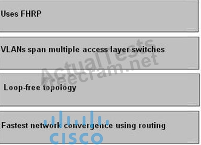
Layer 2 between distribution and access layers, with a Layer 3 link between the distribution switches
-> Support Layer 2 VLANs spanning multiple access layer switches across the distribution switches Layer 2 between distribution and access layers, with a Layer 2 link between the distribution switches
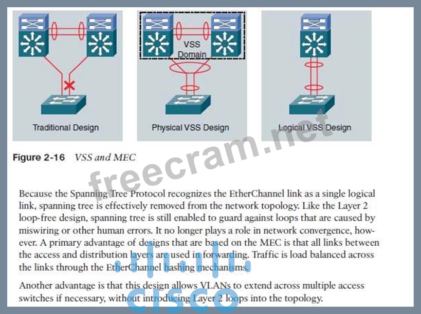
-> FHRP for convergence, no VLANs span between access layer switches across the distribution switches VSS -> Convergence (FHRP) is not an issue The following are recommended best practices at the distribution layer:
Cisco Press CCDA 640-864 Official Certification Guide Fourth Edition, Chapter 3


- Question List (158q)
- Question 1: During which phase of the PPDIOO model would you conduct int...
- Question 2: You are designing a network that requires a routing protocol...
- Question 3: Which three solutions are part of the Borderless Network Ser...
- Question 4: You want to gather as much detail as possible during a netwo...
- Question 5: Which three are features of LWAPP? (Choose three.)...
- Question 6: When selecting which hardware switches to use throughout an ...
- Question 7: Which is a factor in enterprise campus design decisions?...
- Question 8: (Exhibit) Select and Place: (Exhibit)...
- Question 9: Which two are types of network virtualization? (Choose two.)...
- Question 10: Which layer of the OSI model does Cisco recommend to place t...
- Question 11: (Exhibit) Select and Place: (Exhibit)...
- Question 12: Which statement describes the recommended deployment of DNS ...
- Question 13: Which two are characteristics of a Lightweight Access Point?...
- Question 14: Which network access control technology is recommended to us...
- Question 15: Which voice codec should you use in order to provide toll qu...
- Question 16: Which network virtualization technology involves creating vi...
- Question 17: (Exhibit) Select and Place: (Exhibit)...
- Question 18: Refer to the exhibit. (Exhibit) Which three modules would ty...
- Question 19: A hierarchical design of the EIGRP domain facilitates which ...
- Question 20: Which two routing protocols operate over NBMA point-to-multi...
- Question 21: (Exhibit) Select and Place: (Exhibit)...
- Question 22: Which three modular components are part of the Cisco Enterpr...
- Question 23: Which WLC interface is dedicated for WLAN client data?...
- Question 24: Which of these statements is true concerning the data center...
- Question 25: Which of the following is a component within the Cisco Enter...
- Question 26: Which two design approaches provide management of enterprise...
- Question 27: Characterizing an existing network requires gathering as muc...
- Question 28: According to Cisco, which four improvements are the main ben...
- Question 29: (Exhibit) Select and Place: (Exhibit)...
- Question 30: You have a campus network that consists of only Cisco device...
- Question 31: Refer to the exhibit. (Exhibit) A standard, Layer 2 campus n...
- Question 32: What is a characteristic of campus core designs?...
- Question 33: Which Gigabit Ethernet media type provides the longest reach...
- Question 34: Which three describe challenges that are faced when deployin...
- Question 35: Which of the following three options represents the componen...
- Question 36: Which mode is used to exclusively look for unauthorized acce...
- Question 37: Which one of these statements is an example of how trust and...
- Question 38: Which two link state routing protocols support IPv6 routing?...
- Question 39: (Exhibit) Select and Place: (Exhibit)...
- Question 40: (Exhibit) Select and Place: (Exhibit)...
- Question 41: Which Cisco device has the sole function at looking at threa...
- Question 42: Which Cisco technology using Nexus NX-OS infrastructure allo...
- Question 43: An enterprise campus module is typically made up of four sub...
- Question 44: (Exhibit) Select and Place: (Exhibit)...
- Question 45: When designing the threat detection and mitigation portion f...
- Question 46: Which three are security services offered through Cisco Rout...
- Question 47: (Exhibit) Select and Place: (Exhibit)...
- Question 48: Which statement describes a unique advantage of EIGRP?...
- Question 49: A campus network needs end-to-end QoS tools to manage traffi...
- Question 50: Which two statements about designing the Data Center Access ...
- Question 51: Which four services does the architecture for Media Services...
- Question 52: When designing the identity and access control portions for ...
- Question 53: Which is usually used to connect to an upstream ISP?...
- Question 54: Which one of these statements should the designer keep in mi...
- Question 55: You need to connect to a remote branch office via an Interne...
- Question 56: Your company's Cisco routers are operating with EIGRP.You ne...
- Question 57: OSPF will be used as the IGP within a campus network. Which ...
- Question 58: Which IGP provides the fastest convergence by default?...
- Question 59: What are the three modes of unicast reverse path forwarding?...
- Question 60: You are tasked with designing a new branch office that will ...
- Question 61: When designing using the Cisco Enterprise Architecture, in w...
- Question 62: A company wants to use private IP addresses for all its inte...
- Question 63: Which three service categories are supported by an ISR? (Cho...
- Question 64: Which is the North American RIR for IPv4 addresses?...
- Question 65: When designing an EIGRP network, which two things should you...
- Question 66: In which phase of PPDIOO are the network requirements identi...
- Question 67: Which factor would be most influential in choosing multimode...
- Question 68: Cisco Identity-Based Networking Services relies heavily on t...
- Question 69: Which servers that reside in the data center require direct ...
- Question 70: To provide Layer 2 connectivity between the primary and remo...
- Question 71: Data Center Design 3.0 (Exhibit) Select and Place: (Exhibit)...
- Question 72: You are asked to design a new branch office that will need t...
- Question 73: Which two routing protocols converge most quickly? (Choose t...
- Question 74: Which two features are supported by single wireless controll...
- Question 75: What are three key areas that need to be considered when des...
- Question 76: (Exhibit) Select and Place: (Exhibit)...
- Question 77: What is the maximum number of groups that is supported by GL...
- Question 78: Which two common cable management strategies are used in hig...
- Question 79: Which three technologies are recommended to be used for WAN ...
- Question 80: Which two enterprise campus layers are combined in a medium-...
- Question 81: Refer to the exhibit. (Exhibit) Which layer is the distribut...
- Question 82: (Exhibit) Select and Place: (Exhibit)...
- Question 83: (Exhibit) Select and Place: (Exhibit)...
- Question 84: A company is implementing an Identity Management solution wi...
- Question 85: Which consideration is the most important for the network de...
- Question 86: Which three protocols support VLSM? (Choose three.)...
- Question 87: The enterprise campus core layer has requirements that are u...
- Question 88: Which three are considered as technical constraints when ide...
- Question 89: (Exhibit) Select and Place: (Exhibit)...
- Question 90: Where in the Cisco Enterprise Architecture model does networ...
- Question 91: (Exhibit) Select and Place: (Exhibit)...
- Question 92: Which three options are valid Cisco STP tools used to ensure...
- Question 93: The evolution of the Data Center is best represented by the ...
- Question 94: Which is the purpose of the Cisco NAC Profiler?...
- Question 95: With deterministic Wireless LAN Controller redundancy design...
- Question 96: If a teleworker is required to access the branch office via ...
- Question 97: (Exhibit) Select and Place: (Exhibit)...
- Question 98: What is the recommended spanning tree protocol to use for al...
- Question 99: (Exhibit) Select and Place: (Exhibit)...
- Question 100: (Exhibit) Select and Place: (Exhibit)...
- Question 101: Which IPv6 feature enables routing to distribute connection ...
- Question 102: (Exhibit) Select and Place: (Exhibit)...
- Question 103: (Exhibit) Select and Place: (Exhibit)...
- Question 104: Which protocol is the recommended first-hop redundancy proto...
- Question 105: What are the three primary functions of the distribution lay...
- Question 106: When designing a WAN backup for voice and video applications...
- Question 107: Your supervisor has asked you to deploy a routing protocol w...
- Question 108: Which type of area should you use in an enterprise OSPF depl...
- Question 109: With respect to IPv6 addressing, from a design perspective, ...
- Question 110: Which WAN technology is a cost-effective method to deliver 1...
- Question 111: Which three are valid Layer 2 access designs? (Choose three....
- Question 112: Which two devices would you place in your DMZ to ensure ente...
- Question 113: Which two of the following are benefits of using a modular a...
- Question 114: When designing the infrastructure protection portion for the...
- Question 115: Refer to the exhibit. (Exhibit) Which two statements correct...
- Question 116: When considering the three VoIP design models - single site,...
- Question 117: Which is part of the Prepare phase of PPDIOO?...
- Question 118: At which layer of the network is route summarization recomme...
- Question 119: Refer to the exhibit. (Exhibit) Which statement is true conc...
- Question 120: Refer to the list of requirements. Which IP telephony design...
- Question 121: Which two can be used as a branch office WAN solution? (Choo...
- Question 122: Which three types of WAN topologies can be deployed in the S...
- Question 123: (Exhibit) Select and Place: (Exhibit)...
- Question 124: When designing for a remote worker, which two are typical re...
- Question 125: What is the acceptable amount of one-way network delay for v...
- Question 126: In the enterprise data center, which are the three main comp...
- Question 127: (Exhibit) Select and Place: (Exhibit)...
- Question 128: Which technology enables WLCs to peer with each other to ena...
- Question 129: Which protocol is used for voice bearer traffic?...
- Question 130: When there is a need for immunity to EMI for connecting loca...
- Question 131: Which one of these statements describes why, from a design p...
- Question 132: Which three statements are true regarding the virtual interf...
- Question 133: When you are designing a large IPv6 multivendor network, whi...
- Question 134: Which three are associated with the distribution layer withi...
- Question 135: (Exhibit) Select and Place: (Exhibit)...
- Question 136: Which two statements best describe an OSPF deployment?(Choos...
- Question 137: WAN backup over the Internet is often used to provide primar...
- Question 138: Which routing protocol classification should you use when fu...
- Question 139: (Exhibit) Select and Place: (Exhibit)...
- Question 140: ACME corporation is implementing dynamic routing on the LAN ...
- Question 141: When designing the infrastructure protection portion for the...
- Question 142: Which two of these practices are considered to be best pract...
- Question 143: What is the most compact representation of the following IPv...
- Question 144: Which of these is the equation used to derive a 64 Kbps bit ...
- Question 145: (Exhibit) Select and Place: (Exhibit)...
- Question 146: (Exhibit) Select and Place: (Exhibit)...
- Question 147: (Exhibit) Select and Place: (Exhibit)...
- Question 148: Which subnet address and mask would you use for all Class D ...
- Question 149: Which one of these statements is true concerning the data ce...
- Question 150: Which protocol is used to reserve bandwidth for the transpor...
- Question 151: Which model of ISR is utilized for the teleworker design pro...
- Question 152: Which three items pertain to EIGRP? (Choose three.)...
- Question 153: (Exhibit) Select and Place: (Exhibit)...
- Question 154: Refer to the exhibit. (Exhibit) Which statement accurately r...
- Question 155: What is the primary consideration when choosing a routed net...
- Question 156: Spanning Layer 2 across geographically separate data centers...
- Question 157: Your supervisor wants you to recommend a management protocol...
- Question 158: High availability is a key design consideration in the enter...
